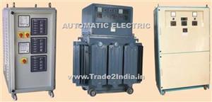
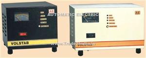
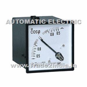
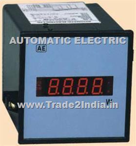
Highest quality standards are achieved through the implementations of latest technology, decades of experience and everlasting moral values , which have helped us to retain our customers as well as multiply them.
FEATURES | |
• | Microprocessor controlled |
• | Self zero check and calibration check |
• | Digital display of %input, ratio error and phase error |
• | Manual and auto ranging modes |
• | Test 5A and 1A CT with either 1A or 5A reference CT |
• | RS 232C port and parallel port for printing |
• | Built in real time clock |
• | Parameter entry through keyboard |
ELECTRICAL SPECIFICATIONS | ||
• | TYPE | SINGLE PHASE |
• | OPRATING CURRENT | I A / 5A, 0.5VA |
• | AUXILIARY SUPPLY | 110V/240V,AC ±20%, 50/60Hz, 60VA. |
• | ACCURACY | ± 0.5% of reading ±1 % of range |
• | FREQUENCY | 45Hz to 55Hz or 55Hz to 65Hz. |
• | ERROR RANGES | 20% (±19.99% ratio error and (±19.99cR* or 680mins.phase error)) |
2% (±1.999% and (±1.999cR or 68.0 mins.)) | ||
0.2% (±1999ppm and (±1999µR or 6.80 mins.)) | ||
(cR = Centiradians, µR = Microradians, ppm = Parts Per Million). | ||
• | RESOLUTION | 0.05% of range |
• | MEASURING TIME | 7 seconds irrespective of signal level and error range. |
• | OUTPUTS | RS232C port & Parallel port (data in ASCII format). |
• | INSULATION RESISTANCE | Greater than 20 Mohms at 500V. DC. |
• | DIELECTRIC STRENGTH | 2kV RMS for 1 minute |
• | OPERATING TEMP. | 0°C to 55°C |
• | STORAGE TEMP. | -20°C to 70°C |
• | HUMIDITY | Upto 95% RH. |
MECHANICAL SPECIFICATIONS | ||
• | MODEL | CTU |
• | SIZE | 180x320x450mm |
• | WEIGHT (Appro.) | 8.0Kgs |
KEYBOARD CONTROLS | |
0 - 9 | Numeric keys to enter values. |
• | Decimal point. |
ENT | Enter key |
RTC | Enter date and time. |
SR / VA | Enter serial no. and burden. |
Take printout of error readings. | |
SER | Send data to serial port. |
% / ACT | Display input in percentage or actual value. |
DEG/RAD | Display phase error in minutes or centiradians. |
ZERO | Check auto zero. |
CAL | Test self calibration. |
DISPLAYS AND INDICATIONS | |
• | 4 digit LED display each to display input, ratio error and phase error. |
• | LED indications for following quantities |
1) % Input | |
2) Minutes and centiradians. | |
3) Range for 20%, 2%, 0,2% and Auto | |
4) Balance, overrange, zero and calibration. |
PRINTING | |
Date, time, serial no., input (% or actual value), burden, %ratio error, & phase error (minutes or centiradians). |
Ordering information |
1) Type 2) Model 3) Operating current 4)Operating Frequency 5)Auxiliary supply |
INTRODUCTION | |
Every electrical apparatus or machine Is provided with insulation between live part and earth or between two different sections of live parts. This insulation is required to be tested at high voltage values recommended by applicable relevant standards. |
|
High Voltage Tests Sets of higher voltage upto 600kV are also manufactured against specific requirement. The standard voltages are 10kV, 15kV, 20kV, 25kV, 30kV, 50kV,100kV, 150kV, 200kV & 300kV. The test sets uplo 30kV are manufactured in Air Cooled design while the sets of 50kV & above are manufactured in Oil Cooled design. The output of these high voltage testers is single phase 50/60Hz. The standard H.T. current rating of air-cooled design as also of oil cooled design upto 150kV is 100mA for 30 minutes. For voltages ranges above 'AE' make 5kV A.C. (with 2.5kV tap) High Voltage Breakdown Tester is portable, sturdy & plug in to start type construction & requires minium table space. It broadly consists of 3 main sections. |
1) HIGH VOLATGE TRANSFORMER : | |
The High voltage transformer is single phase, single pole type & is of double wound resin moulded |
|
2) VARIABLE VOLTAGE SOURCE : | |
Variable Voltage supply is provided through a Dimmerslat (Variable auto-transformer) havingasuitable rating corresponding to the rating of H.V. Transformer. Dimmerstat Is rated for 230Volts A.C. input & 0-270V output. Limit switch at zero position end of Dimmerstat winding is provided to facilitate the H.T. winding to |
|
3) CONTROL CIRCUIT & OTHER FEATURES : | |
• |
ManuaIly operated control transformer (VariabIe auto-transformer) with zero interlock facility. |
• |
72mm sq. double range (0-2kV / 0-5kV) moving coil rectifier type voltmeter of class 1.5, provided to read NO LOAD H.T. Voltage. |
• |
72mm sq. double range (0-100mA) moving coil rectifier type A.C. Milliammeter of class 1.5, provided in the earth end of the H.T. winding to read H.T. Current. |
• |
Automatic tripping circuit is provided for isolation of supply, in the event of failure of the object under test. Rotary switch with four different settings of 5,10, 50 & 100mA is provided on front panel with LED indication |
• |
M.C.B. for short circuit protection of H.T. transformer & auto transforme |
• |
H.T. ON push button, Mains ON & H.T ON LED indication. |
• |
Range selection switch to select 2.5kV or 5kV range with LED indication. |
• |
Two spring loaded test prods with 1 metre long cable for safe & easy connection of high voltage to test object, (upto 5kV.) |
DESCRIPTION |
It compares & reads the error due to imbalance in signals of test P.T. with reference P.T. and applies necessary proportional signal to nullify the error. Input is displayed in percentage or actual value, and phase error in centiradians or minutes. On separate key commands the error readings with date, time,% input & burden are sent either to a PC through RS232C port or to a printer connected to parallel port, in order to have report in "view format". The data read from RS232C port can be arranged by using any standard text editor, and a printout can be taken. |
FEATURES | |
• | Micro processor controlled |
• | Self zero check and calibration check |
• | Digital display of %input, ratio error and phase error. |
• | Programmable voltage input |
• | Manual and auto ranging modes |
• | RS 232C port and parallel port for printing |
• | Built in real time clock |
• | Parameter entry through keyboard |
ELECTRICAL SPECIFICATIONS | ||
• | TYPE | Single phase |
• | OPERATING VOLTAGE | 3 to 110V AC, 0.5VA |
• | AUXILLARY SUPPLY | 11OV / 240V. AC ±20%, 50 / 60Hz, 60VA. |
• | ACCU RACY | ±0.5% of rdg ±1 %of range |
• | FREQUENCY | 45Hz to 55Hz or 55Hz to 65Hz |
• | ERROR RANGES | 20% (±19.99% ratio error and (±19.99cR* or 680 mins.phase error)) |
2%(±1.999% and (±1.999cR or 68.0 mins.)) | ||
0.2%(±1999ppm and (±1999µR or 6.80 mins.)) | ||
(cR = Centiradians, µR = Microradians, ppm = Parts Per Million). | ||
• | RESOLUTION | 0.1 Vac |
• | MEASURING TIME | 7 seconds, irrespective of signal level and error range. |
• | OUTPUTS | RS232C port & Parallel port (data in ASCII format). |
• | INSULATION RESISTANCE | Greater than 20 Mohms at 500V. DC. |
• | DIELECTRIC STRENGTH | 2kV RMS for 1 minute |
• | OPERATING TEMP. | 0°C to 55°C |
• | STORAGE TEMP. | - 20°C to 70°C |
• | HUMIDITY | Upto 95% RH |
MECHANICAL SPECIFICATIONS | ||
• | MODEL | PTU |
• | SIZE | 180 x 320 x 450 mm |
• | WEIGHT(Appro.) | 8.0 kg. |
KEYBOARD CONTROLS | |
0 - 9 | Numeric keys to enter values. |
. | Decimal point. |
ENT | Enter key. And also to enter voltage input. |
RTC | Enter date and time. |
SR / VA | Enter serial no. and burden. |
Take printout of error readings. | |
SER | Send data to serial port. |
% / ACT | Display input in percentage or actual value. |
DEG / RAD | Display phase error in minutes or centiradians. |
ZERO | Check auto zero. |
CAL | Test self calibration. |
DISPLAYS and INDICATIONS | |
• | 4Digit LED display to indicate input voltage, ratio error and phase error. |
• | LED indications for following quantities |
1) % Input | |
2) Minutes and centiradians. | |
3) Range for 20%, 2%, 0.2% and Auto | |
4) Balance, overrange, zero and callibration. |
PRINTING |
Date, time, serial no., input(% or actual value), burden, % ratio error, & phase error (minutes or centiradians). |
Ordering information |
1) Type 2) Model 3) Operating voltage 4) Operating frequency. |
Description / Specification of Current Transformer
We are involved in offering a wide range of Current Transformer to our most valued clients. Our range of these are widely appreciated by our clients which are situated all round the nation. We offer our range of it at most affordable prices.
We introduce ourselves as an eminent trader and supplier of an extensive array of Current Transformer. Prior to dispatch, our quality controllers run numerous tests on the entire range on various parameters of quality and durability. The offered equipment is manufactured using superior quality components with the aid of sophisticated techniques at the vendors' end. Moreover, our precious clients can purchase it in different technical specifications at reasonable price from us within promised time frame.
Features:
Sturdy design
Highly durable
Application specific design
Description / Specification of Voltage Transformer
We are involved in offering a wide range of Voltage Transformer to our most valued clients. Our range of these are widely appreciated by our clients which are situated all round the nation. We offer our range of it at most affordable prices.
We introduce ourselves as an eminent trader and supplier of an extensive array of Voltage Transformer. Prior to dispatch, our quality controllers run numerous tests on the entire range on various parameters of quality and durability. The offered equipment is manufactured using superior quality components with the aid of sophisticated techniques at the vendors' end. Moreover, our precious clients can purchase it in different technical specifications at reasonable price from us within promised time frame.
Features:
Sturdy design
Highly durable
Application specific design
Description / Specification of Encapsulated Current Transformers Ae 110 (86) Series
We are involved in offering a wide range of Encapsulated Current Transformers Ae 110 (86) Series to our most valued clients. Our range of these are widely appreciated by our clients which are situated all round the nation. We offer our range of it at most affordable prices.
We introduce ourselves as an eminent trader and supplier of an extensive array of Encapsulated Current Transformers Ae 110 (86) Series. Prior to dispatch, our quality controllers run numerous tests on the entire range on various parameters of quality and durability. The offered equipment is manufactured using superior quality components with the aid of sophisticated techniques at the vendors' end. Moreover, our precious clients can purchase it in different technical specifications at reasonable price from us within promised time frame.
Features:
Sturdy design
Highly durable
Application specific design
Description / Specification of Encapsulated Current Transformers Ae 125 (104) Series
We are involved in offering a wide range of Encapsulated Current Transformers Ae 125 (104) Series to our most valued clients. Our range of these are widely appreciated by our clients which are situated all round the nation. We offer our range of it at most affordable prices.
We introduce ourselves as an eminent trader and supplier of an extensive array of Encapsulated Current Transformers Ae 125 (104) Series. Prior to dispatch, our quality controllers run numerous tests on the entire range on various parameters of quality and durability. The offered equipment is manufactured using superior quality components with the aid of sophisticated techniques at the vendors' end. Moreover, our precious clients can purchase it in different technical specifications at reasonable price from us within promised time frame.
Features:
Sturdy design
Highly durable
Application specific design
Description / Specification of Encapsulated Current Transformers Ae 65 (45) Series
We are involved in offering a wide range of Encapsulated Current Transformers Ae 65 (45) Series to our most valued clients. Our range of these are widely appreciated by our clients which are situated all round the nation. We offer our range of it at most affordable prices.
We introduce ourselves as an eminent trader and supplier of an extensive array of Encapsulated Current Transformers Ae 65 (45) Series. Prior to dispatch, our quality controllers run numerous tests on the entire range on various parameters of quality and durability. The offered equipment is manufactured using superior quality components with the aid of sophisticated techniques at the vendors' end. Moreover, our precious clients can purchase it in different technical specifications at reasonable price from us within promised time frame.
Features:
Sturdy design
Highly durable
Application specific design
Description / Specification of Encapsulated Current Transformers Ae 78 (62) Series
We are involved in offering a wide range of Encapsulated Current Transformers Ae 78 (62) Series to our most valued clients. Our range of these are widely appreciated by our clients which are situated all round the nation. We offer our range of it at most affordable prices.
We introduce ourselves as an eminent trader and supplier of an extensive array of Encapsulated Current Transformers Ae 78 (62) Series. Prior to dispatch, our quality controllers run numerous tests on the entire range on various parameters of quality and durability. The offered equipment is manufactured using superior quality components with the aid of sophisticated techniques at the vendors' end. Moreover, our precious clients can purchase it in different technical specifications at reasonable price from us within promised time frame.
Features:
Sturdy design
Highly durable
Application specific design
Description / Specification of Encapsulatedcurrent Transformers Ae 155 (140) Series
We are involved in offering a wide range of Encapsulatedcurrent Transformers Ae 155 (140) Series to our most valued clients. Our range of these are widely appreciated by our clients which are situated all round the nation. We offer our range of it at most affordable prices.
We introduce ourselves as an eminent trader and supplier of an extensive array of Encapsulatedcurrent Transformers Ae 155 (140) Series. Prior to dispatch, our quality controllers run numerous tests on the entire range on various parameters of quality and durability. The offered equipment is manufactured using superior quality components with the aid of sophisticated techniques at the vendors' end. Moreover, our precious clients can purchase it in different technical specifications at reasonable price from us within promised time frame.
Features:
Sturdy design
Highly durable
Application specific design
Description / Specification of Encapsulated Current Transformers Ae 70 (50) Series
We are involved in offering a wide range of Encapsulated Current Transformers Ae 70 (50) Series to our most valued clients. Our range of these are widely appreciated by our clients which are situated all round the nation. We offer our range of it at most affordable prices.
We introduce ourselves as an eminent trader and supplier of an extensive array of Encapsulated Current Transformers Ae 70 (50) Series. Prior to dispatch, our quality controllers run numerous tests on the entire range on various parameters of quality and durability. The offered equipment is manufactured using superior quality components with the aid of sophisticated techniques at the vendors' end. Moreover, our precious clients can purchase it in different technical specifications at reasonable price from us within promised time frame.
Features:
Sturdy design
Highly durable
Application specific design
Description / Specification of Encapsulated Current Transformers Ae 98 (74) Series
We are involved in offering a wide range of Encapsulated Current Transformers Ae 98 (74) Series to our most valued clients. Our range of these are widely appreciated by our clients which are situated all round the nation. We offer our range of it at most affordable prices.
We introduce ourselves as an eminent trader and supplier of an extensive array of Encapsulated Current Transformers Ae 98 (74) Series. Prior to dispatch, our quality controllers run numerous tests on the entire range on various parameters of quality and durability. The offered equipment is manufactured using superior quality components with the aid of sophisticated techniques at the vendors' end. Moreover, our precious clients can purchase it in different technical specifications at reasonable price from us within promised time frame.
Features:
Sturdy design
Highly durable
Application specific design
RANGE OF MANUFACTURE : | |
1. Tapewound ring type current Transformers with and without mounting arrangements. 2. Tapewound ring type CTs with sealing arrangements. 3. Tapewound wound primary CTs (WPL) 4. Resincast (epoxy) BPL CTs. 5. Resincast (epoxy) wound primary (WPL) CTs. 6. Bushing CTs (Fibreglass taped). |
|
CORE BALANCE CTs (Resincast) : | |
These are used in detecting earth faults of very small magnitude. A three phase cable is passed through these CTs & the unbalanced currents in the three phases set up a differential flux giving rise to a current on the secondary side of these CTs sufficient to actuate a relay. | |
INTERPOSING CURRENT TRANSFORMERS (Resincast) : | |
Used in matching the ratios of main feeder CTs for differential protection schemes. These also find application as saturable CTs used in conjunction with main feeder CTs and thus protect the meters connected to these by limiting the current flowing through the meters. | |
SUMMATION CTs (Resincast) : | |
Current transformers intended to summate the currents in a number of feeders in association with the feeder Cts is called summation Transformer. The performance / testing of these CTs are governed by IS-6949-1973, BS-3938, IEC-185. | |
BUSHING CTs (Fibreglass Taped) : | |
Widely used by Transformer manufacturers for use in oil. | |
PORTABLE CTs | |
With class 0.2 accuracy for metering & testing purpose. | |
FURNACE CTs | |
CTs WITH ABS CASING AND WITH SEALING ARRANGEMENTS : | |
Widely used by Electricity Board along with Energy meters. | |
LOW TENSION POTENTIAL TRANSFORMER (Tapewound / Resincast) : | |
These are offered in various ratios from 1100/110V to 50/ 75V to suit the exact applications of the clients. Rated burdens upto IOOVA with accuracy classes of I or 0.5 can be offered. Various other types of low tension instruments transformers are also manufactured by us to suit the exact requirements of our clients. Our team of specialised Engineers will be pleased to be of assistance to the clients in proper selection of instrument transformers for their applications. | |
PROTECTION AND CLASS PS (CLASS X) CTs BOTH IN TAPEWOUND / RESINCAST : | |
CTs, With class 'PS'/ class'X'for differential protection / BUS coupler application. |
DESCRIPTION | ||
AE makes L. T. Transformers in different types & capacities to suit individual requirments. a) Single phase / Three phase, Double wound / Auto wound, Air cooled / Oil cooled. b) Any special (LT) transformer including ultra-isolation transformer. c) Other types of transformers upto 600kA. i) Lighting Tranformer ii) Extra Low Votlage Loading Transformer used for current injection sets iii) Furnace Transformer suitables for use with thyritor controlled furnaces iv) Motor starting Auto Transformer upto 600kA. v) Other as per customer specifications. d) For voltages beyond 660 Volts &7 frequencies other than 50Hz, special construction possible as per customer specifications. |
Features | |||
• | Simple - rugged construction, in ssheet steel enclosure / tank. | ||
• | Coils made from high grade CRGO & 99.9% pure copper. | ||
• | High efficiency upto 98.5%. | ||
• | Excellent short time overload capacity. | ||
• | Operating temperature - 45° C. | ||
• | Insulation class - 'B' (higher on request) | ||
• | Conforms to IS 2026. | ||
• | Suitables for indoor use. |
Mechanical Construction | |
• | Terminal accessible through cable entry holes or on opening terminal box. |
• | Floor mounting transformers may be provided with MS rollers or base channel. |
• | Wall mounting arrangement, wherever feasible can be provided. |
• | Off load taps - controlled by link arrangement of tap selector switch. |
• | Open transformers without enclosure can be provided for mounting inside a control panel or cubicle |
DESCRIPTION |
Dimmerstat' is registered trade mark for AE make continuously variable voltage auto-transformer. It is the most effective device for stepless, breakless & continuous control of AC voltage & therefore for various parameters, dependent on AC voltage. |
The basic Dimmerstat is meant for operation from a nominal input voltage of 240V 1ph AC & can give output voltage anywhere between 0 to 240V or 0 to 270V AC by simple transformer action. Three such Dimmerstats connected electrically in star and mechanically in tandem, become suitable for operation from a nominal input voltage of 415V 3Ph AC and can give output anywhere between 0 to 415V or 0 to 470V. |
FEATURES | |
• | Simple, rugged construction. |
• | Coils made from high grade CRGO Silicon Steel & 99.9% pure copper. |
• | Output voltage variation is smooth, continuous, breakless & linearly proportional to angular rotation. |
• | High efficiency. |
• | Negligible waveform & power factor distortion. |
• | Excellent short time overload capacity. |
• | Remote operation possible by motorization. |
• | Wide range of current ratings. |
• | High quality carbon brush used for current collection. |
ELECTRICAL SPECIFICATIONS | ||||||||||||||||
• | MODEL | a) Flush Open Manual (Air Cooled) — F | ||||||||||||||
b) Portable Enclosed Manual (Air Cooled) — P | ||||||||||||||||
c) In Tank Manual (Oil Cooled) — T 'F', 'P', T suffixed by 'M' means motor operated models. |
||||||||||||||||
• | OPERATING VOLTAGE | For Single Phase - 240V AC, 50-60 Hz. 1- ph. | ||||||||||||||
For Three Phase - 415V AC, 50 -60 Hz., 3 - ph - 4wire. | ||||||||||||||||
• | CURRENT RATINGS | For Oil Cooled models, maximum current & continuouscurrent are one & the same. | ||||||||||||||
For Air Cooled models, the ratings are as shown below. | ||||||||||||||||
Maximum Current | 0.7 | 2 | 4 | 8 | 10 | 15 | 20 | 28 | ||||||||
Continuous Current | 0.6 | 1.8 | 3.8 | 6.5 | 9 | 11.5 | 16 | 22 | ||||||||
• | OPERATING TEMP. | 0° - 45°C. | ||||||||||||||
• | INSULATION RESISTANCE | Not less than 5 Mohms at 500V DC. | ||||||||||||||
• | DIELECTRIC TEST | 2.5kV RMS for 1 minute. | ||||||||||||||
• | STORAGE TEMP. | -9°C to 70°C | ||||||||||||||
• | HUMIDITY | Upto 95% RH | ||||||||||||||
• | CONFORMS TO | I.S. 5142. |
Notes : | |
1 | As output voltage is continuously variable, Dimmerstats are rated in terms of current that can be drawn from the output. |
2 | Oil should be "Transformer Oil" conforming to IS 335, IEC 296. |
MECHANICAL CONSTRUCTION | |
Single phase Dimmerstats are available in 3 types. | |
• | Portable type (P) with sheet steel enclosure for floor / table use. |
• | Flush type (F) with open type construction. Suitable for panel mounting. |
• | Tank type (T) immersed in oil in sheet steel tank with rollers. |
Three phase Dimmerstat is usually ganged assembly of 3 coils, available in all 3 types: P, F, T. |
Higher rating Dimmerstat (above 200 Amps) use 2/3 or more coils in parallel with load balancing arrangements. |
Motorised Dimmerstat uses 240V AC Step-Syn Motor having 60 rpm speed at 50Hz. With proper gearing higher torque at lower speed can be achieved. Standard gear ratios used provide sweep time of 8, 15, 30, 45, 60,120secs. |
APPLICATIONS | |
• | Auditorium, Hotels, Conference Halls, Exhibitions, Laboratories etc., |
• | AC Voltage Stabilizers, Rectifiers, Battery Chargers. |
• | Temperature control of Ovens, Furnaces. |
• | Testing of Instruments, Relays, Circuit Breakers etc. |
• | Welding, Electro-plating, Anodizing etc. |
• | Colleges & Universities. |
Ordering Information (as per code specified below) | ||
1st block | Output current rating amps |
0.7,2,4,8,10,15,20,28,40,50,60,75,100,125,150, 200,300,400, 500,600,800,1000,1200,1500 A. |
2nd block | Dimmerstat (D) | Continuously variable voltage auto transformer. |
3rd block | No. of coils | 1, 2, 3, 4, 6, 9, 12, 15. |
4th block | Type of construction. | F, P, T F = Flush, back of panel open. P = Portable, floor, table mounting, air cooled with enclosure. T = In tank, immersed in oil. |
5th block | Provided with motor drive (M) |
"Step-syn" 230V 1Ph AC 50Hz. 60 rpm motor having instantaneous start-stop-reverse characteristics. |
6th block | Approx. time in secs. for full rotation sweep time | 8,15,30,45,60,120 |
e.g. | 1 | 2 | 3 | 4 | 5 | 6 | 75 A Dimmerstat with 3 coils (Three phase) in oil-cooled tank construction with motor drive having 15 sec. sweep. |
75 | D | 3 | T | M | 15 |
e.g. | 1 | 2 | 3 | 4 | 8 A Dimmerstat with 1coil (Single phase). Portable type & suitable for manual operation (no motorisation) |
||
8 | D | 1 | P |
Simiarly, other Dimmerstats can be configured & ordered. |
Description / Specification of Current Injection Test Unit
We are involved in offering a wide range of Current Injection Test Unit to our most valued clients. Our range of these are widely appreciated by our clients which are situated all round the nation. We offer our range of it at most affordable prices.
We introduce ourselves as an eminent trader and supplier of an extensive array of Current Injection Test Unit. Prior to dispatch, our quality controllers run numerous tests on the entire range on various parameters of quality and durability. The offered equipment is manufactured using superior quality components with the aid of sophisticated techniques at the vendors' end. Moreover, our precious clients can purchase it in different technical specifications at reasonable price from us within promised time frame.
Features:
Sturdy design
Highly durable
Application specific design
DESCRIPTION |
These are basically two phase motors. Two-phase supply is normally not available, hence to operate the motors from single phase AC supply, second phase is artificially created by inserting a Capacitor and Resistor combination in series with one of the motor phase windings. Suitable combination of Capacitor and Resistor assembly is supplied along with the motor. The speed of revolution is 60 RPM at 50Hz. Instant stop & reversibility are achieved by means of a single-pole, double throw switch with center OFF position. |
FEATURES | |
• |
Instant start & stop. |
• |
The motors have permanent magnet on the toothed rotor. The rotor is locked with matching teeth on stator, as soon as power is switched OFF. |
• | Starting & running current are same. |
• | Maximum Torque is 15 to 20% higher than nominal torque. |
ELECTRICAL SPECIFICATIONS | |||||
TYPE ? | SS-32 | SS-72 | SS-102 | SS-202 | SS-302 |
VOLTAGE | 240V.A.C. | 240V.A.C. | 240V.A.C. | 240V.A.C. | 240V.A.C. |
CURRENT | 100mA | 100mA | 200mA | 300mA | 500mA |
RESISTOR | 1kO / 15W | 1kO / 15W | 1.8kO / 20W | 800O / 100W | 235O / 200W |
CAPACITOR | 0.7mfd / 400V.A.C. |
0.7mfd / 400V.A.C. |
1.0mfd / 400V.A.C. |
3.0mfd / 400V.A.C. |
4.0mfd / 400V.A.C. |
NOM.TORQUE | 3kg cm | 7kg cm | 10kg cm | 20kg cm | 30kg cm |
MECHANICAL SPECIFICATIONS | |||||||||
DIMENSIONS ? TYPE ? |
A | B | C | D | E | F | G | ØH | WT. kg |
SS-32 / SS-72 | 87SQ. | 8 | 25 | 70 | 17 | 112 | 70SQ. | 7 | 1.3 |
SS-102 | 108SQ. | 9 | 25 | 75 | 12 | 112 | 85SQ. | 8 | 2.0 |
All dimensions are in mm. | |||||||||
DIMENSIONS ? TYPE ? |
A | B | C | D | E | F | G | ØH | WT. kg |
SS-202 | 108SQ. | 9 | 34 | 104 | 21 | 159 | 85SQ. | 8 | 3.4 |
SS-302 | 108SQ. | 9 | 34 | 132 | 21 | 187 | 85SQ. | 8 | 4.5 |
All dimensions are in mm. | |||||||||
ORDERING INFORMATION |
1) Type |
Description / Specification of Rectifier Units For Electroplating And Anodising
We are involved in offering a wide range of Rectifier Units For Electroplating And Anodising to our most valued clients. Our range of these are widely appreciated by our clients which are situated all round the nation. We offer our range of it at most affordable prices.
We introduce ourselves as an eminent trader and supplier of an extensive array of Rectifier Units For Electroplating And Anodising. Prior to dispatch, our quality controllers run numerous tests on the entire range on various parameters of quality and durability. The offered equipment is manufactured using superior quality components with the aid of sophisticated techniques at the vendors' end. Moreover, our precious clients can purchase it in different technical specifications at reasonable price from us within promised time frame.
Features:
Sturdy design
Highly durable
Application specific design
Description / Specification of Lighting Transformer Resin Cast Upto 630Kva
We are involved in offering a wide range of Lighting Transformer Resin Cast Upto 630Kva to our most valued clients. Our range of these are widely appreciated by our clients which are situated all round the nation. We offer our range of it at most affordable prices.
We introduce ourselves as an eminent trader and supplier of an extensive array of Lighting Transformer Resin Cast Upto 630Kva. Prior to dispatch, our quality controllers run numerous tests on the entire range on various parameters of quality and durability. The offered equipment is manufactured using superior quality components with the aid of sophisticated techniques at the vendors' end. Moreover, our precious clients can purchase it in different technical specifications at reasonable price from us within promised time frame.
Features:
Sturdy design
Highly durable
Application specific design
Features | |
• | Filters power line noise, spikes and transients. |
• | Isolates sensitive equipment from noisy power lines. |
• | Complete with electrostatic sheilding. |
• | Minimizing common mode noise. |
ELECTRICAL SPECIFICATIONS | ||
Single Phase | Three Phase | |
RATING | 1kVA to 25kVA, 50Hz | 1kVA to 100kVA, 50Hz |
INPUT VOLTAGE | 115V / 230V / 240V nominal | 380 / 415 / 440V nominal. |
ACCEPTABLE INPUT VOLTAGE | ±10 % | |
OUTPUT VOLTAGE | ± 10% | |
MODE of OPERATING | 1:1 Isolation Transformer | |
COMMON MODE NOISE REDUCTION TRANSIENTS, SPIKES, SURGES. | Over 120dB | Over 100dB |
COUPLING CAPACITACE | Less than 0.005pF | Less than 0.05pF |
D.C. GALVANIC ISOLATION | Over 500M O between any winding or winding to the ground. | |
BREAKDOWN STRENGTH | 2.5kV AC for 1 minute. | |
ACCEPTABLE LINE FREQUENCY | 47 Hz to 63 Hz | |
LINE LEAKAGE CURRENT | Less than 25µA | Less than 50µA |
LOAD REGULATION | Within 3% to 4% | Within 3% to 5% |
TERMINATION | On terminal block | On terminal plate |
FINISH | 7 tank pre-treatment, primer coating & two coas of final finish paint. |
DESCRIPTION |
Servo - Controlled Automatic AC Voltage Stabilizers of 'AE' make are of 'Electro - Mechanical (EMS) type. The purpose of voltage stabilizer is to receive a fluctuating AC voltage of large amplitude & deliver an almost constant voltage, which remains within a very narrow band (± 1%) of the nominal voltage - quality of the AC voltage remains unchanged. The voltage variations, which have become a common phenomenon in current power supply system, cause havoc in modern complicated & sophisticated equipments. The voltage stabilizers are meant to take care of this problem & protect the equipments. They ensure longer life of the equipments & also drastically cut down electricity consumption of equipments leading to continuous reduction in electricity bills. Thus, they play an important role in energy conservation which is need of the day. |
The EMS type AC voltage stabilizer basically comprises of the following - | |
• | Dimmerstat (Continuously variable voltage auto transformer). |
• | Buck - Boost Transformer (Optional upto 5kVA 1Ph / 15kVA 3Ph). |
• | AC Step-synchronous motor. |
• | Solid state electronic control circuit. |
• | Two switching triacs. |
• | MOVs for surge suppression. |
FEATURES | |
• | Waveform distortion - nil. |
• | 98 - 99% efficiency (achieved by optimum design & by use of imported hi-quality CRGO laminations & copper of 99.9% purity). |
• | Speed of correction up to 70V/sec. |
• | Response time - less than 20 m/sec. |
• | Immune to load PF & supply frequency variations. |
• | Power loss 2% max. |
• | Duty cycle continuous. |
• | Life expectancy - 20 - 25 years. |
• | Easy & simple maintenance (with plug-in PCBs). |
• | Protections - over voltage / under voltage / overload / single phasing (optional). |
• | Very high reliability. |
• | Considerable short time overload capacity. |
• | Output voltage setting (by potentiometer in Auto Mode & by 'Raise' / 'Lower' Push Button in ManualMode). |
• | Operation - Auto or Manual. |
• | LED Indications for Input Voltage 'High' / 'Low'. |
• | Metering (Analogue or Digital) - AC voltmeter with / without selector switch. |
• | Non-standard requirements can be catered to, such as AC Ammeter, Frequency Meter, PhaseSequence Meter, Single Phasing Preventer, Stabilizer by-pass arrangement, etc. |
ELECTRICAL SPECIFICATIONS | ||
• | MODEL | EMS - 12 |
• | TYPE | Indoor, Floor Mounting. |
• | COOLING | Air - Cooled / Oil Cooled / Air - Oil Cooled. |
• | INPUT | 160 - 260V / 180 - 250V, 1 Phase AC. 300 - 460V / 360 - 460V, 3Phase, 4 Wire (or 3 Wire if required) AC (Balanced or Unbalanced). |
• | OUTPUT | 230V / 240V ± 1%,1 Phase AC. |
380V / 400V / 415V ± 1%, 3Phase AC. | ||
• | CAPACITY | 1 kVA - 2000kVA |
• | FREQUENCY | 50 - 60Hz. |
• | INSULATION RESISTANCE | Not less than 5 Mohms at 500V DC |
• | DIELECTRIC TEST | 1.5kV RMS for 1 minute. |
• | OPERATING TEMP. | 0°C to 50°C |
• | STORAGE TEMP. | - 9°C to 70°C |
• | HUMIDITY | upto 95% RH |
• | CONFORMS TO | I.S.9815 |
NOTES : | |
• | Input & output voltages, other than specified above, are available on specific request. |
• | For 3 Phase balanced supply system, a common controller, connected to any one phase is employed. |
• | For 3 Phase unbalanced supply system, 3 individual & independent controllers, one for each of the 3 Phases, are employed. |
• | Oil should be 'Transformer Oil' Conforming to IS 335, I.E.C. 296. |
MECHANICAL CONSTRUCTION |
APPLICATIONS | |
CNC Machines, Air Compressors, Textile Machines, Lightings, X-ray & Medical Equipments, Engineering Units, Computers, Pump Sets, Transmitters & many other similar applications. |
Ordering information | |
• | Model |
• | Type |
• | Cooling |
• | Input Voltage (Balanced or Unbalanced) |
• | Output Voltage |
• | Capacity (kVA) |
• | Protections (if required) |
• | Non-standard metering. |
• | With / without first filling of oil (only for oil cooled units). |
DESCRIPTION |
The stabilizer consists of a multiple tap auto transformer and solid state control circuit This maintains the output village within ± 12% of nominal voltage for large variations in input voltageI. These can be used for Air conditioners, refrigerators, lights loads etc. |
FEATURES | |
• |
Tripping of output village during under voltage and overvoltage conditions. |
• |
Provision of time delay after startup, under voltage cut of and over voltages cut of conditions. |
• |
In case time delay is not required, then the stabiliser can be switched on by pressing the instant Start push button provided on the front side. |
• | Compact and light weight. |
• | Provision of status LED's for input ON, input On equal voltage (low) and input voltage (High) on the front side. |
TECHNICAL SPECIFICATIONS | |
Input Voltage | : 170V to 270V Ac |
Output voltage | : 225V ± 12% AC |
Output current | : 14Amp |
Capacity | : 4KVA |
Regulation | : Better than 2% |
Under voltage out put | : 140V |
Over voltage out put | : 280V |
Time Delay | : 120 Seconds (Approximately) |
Size | : (250 x 180x170) cubic mm |
Weight | : Max.15kg. (depending on the model). |
AE Manufactures Test bench units Which can be used for several Application of which few are mentioned below. |
|
• | Testing Induction Motors. |
• | Testing of Transformer. |
• | Testing of Analog & Digital meters. |
• | Testing of electrical devices like MCB, MCCB, ACB etc. |
The test enches are coupled with |
Our own make Dimmerstats, |
Stabilizer or Current Injection |
Test kits for carrying out the tests like: |
No load test |
Full load test |
Short circuit test |
Temperature rise test |
Operating characteristics etc. |
ORDERING INFORMATION |
Unit under test |
Complete technical specifications of the unit under test. |
Mechanical dimensions of the test bench desired |
Type of meters reqd- Analog / Digital |
Any other specific features |
RANGE OF MANUFACTURE : | |
1. Tapewound ring type current Transformers with and without mounting arrangements. 2. Tapewound ring type CTs with sealing arrangements. 3. Tapewound wound primary CTs (WPL) 4. Resincast (epoxy) BPL CTs. 5. Resincast (epoxy) wound primary (WPL) CTs. 6. Bushing CTs (Fibreglass taped). |
|
CORE BALANCE CTs (Resincast) : | |
These are used in detecting earth faults of very small magnitude. A three phase cable is passed through these CTs & the unbalanced currents in the three phases set up a differential flux giving rise to a current on the secondary side of these CTs sufficient to actuate a relay. | |
INTERPOSING CURRENT TRANSFORMERS (Resincast) : | |
Used in matching the ratios of main feeder CTs for differential protection schemes. These also find application as saturable CTs used in conjunction with main feeder CTs and thus protect the meters connected to these by limiting the current flowing through the meters. | |
SUMMATION CTs (Resincast) : | |
Current transformers intended to summate the currents in a number of feeders in association with the feeder Cts is called summation Transformer. The performance / testing of these CTs are governed by IS-6949-1973, BS-3938, IEC-185. | |
BUSHING CTs (Fibreglass Taped) : | |
Widely used by Transformer manufacturers for use in oil. | |
PORTABLE CTs | |
With class 0.2 accuracy for metering & testing purpose. | |
FURNACE CTs | |
CTs WITH ABS CASING AND WITH SEALING ARRANGEMENTS : | |
Widely used by Electricity Board along with Energy meters. | |
LOW TENSION POTENTIAL TRANSFORMER (Tapewound / Resincast) : | |
These are offered in various ratios from 1100/110V to 50/ 75V to suit the exact applications of the clients. Rated burdens upto IOOVA with accuracy classes of I or 0.5 can be offered. Various other types of low tension instruments transformers are also manufactured by us to suit the exact requirements of our clients. Our team of specialised Engineers will be pleased to be of assistance to the clients in proper selection of instrument transformers for their applications. | |
PROTECTION AND CLASS PS (CLASS X) CTs BOTH IN TAPEWOUND / RESINCAST : | |
CTs, With class 'PS'/ class'X'for differential protection / BUS coupler application. |
Description / Specification of Digital Panel 16 Range Ammeters
We are involved in offering a wide range of Digital Panel 16 Range Ammeters to our most valued clients. Our range of these are widely appreciated by our clients which are situated all round the nation. We offer our range of it at most affordable prices.
We introduce ourselves as an eminent trader and supplier of an extensive array of Digital Panel 16 Range Ammeters. Prior to dispatch, our quality controllers run numerous tests on the entire range on various parameters of quality and durability. The offered equipment is manufactured using superior quality components with the aid of sophisticated techniques at the vendors' end. Moreover, our precious clients can purchase it in different technical specifications at reasonable price from us within promised time frame.
Features:
Sturdy design
Highly durable
Application specific design
DESCRIPTION |
It incorporates solid state circuitry with micro-controller to measure Power Factor of single phase and three phase system. |
FEATURES | |
?/td> | The Meter does not require external transducer, hence panel wiring is reduced. |
?/td> | Absence of current is indicated by "Err" |
?/td> | Negative sign indicates lagging P.F. |
ELECTRICAL SPECIFICATIONS | ||
?/td> | TYPE | Single phase/Three phase single element |
?/td> | OPERATIG VOLTAGE | 63.5V/110V/240V/440V., 2VA. |
?/td> | OPERATING CURRENT | 1A/5A, 0.5VA. |
?/td> | RESOLUTION | 0.001 |
?/td> | RANGE | 0.1 Lag - 1 - 0.1 Lead |
?/td> | ACCURACY | ?2?/font> |
?/td> | AUXILIARY SUPPLY | 110V / 240V ?0%, 50 / 60 Hz, 3VA. |
?/td> | INSULATION RESISTANCE | Greater than 20 Mohms at 500V DC |
?/td> | DIELECTRIC STRENGTH | 2kV RMS for 1 minute. |
?/td> | OPERATING TEMP. | 0°C to 55? C. |
?/td> | STORAGE TEMP. | -20°C to 70°C. |
?/td> | HUMIDITY | Up to 95% RH. |
?/td> | DISPLAY COLOUR | Red |
MECHANICAL SPECIFICATIONS | ||||
MODEL | PFH 96 D | PFF 96 D | PFH 144 D | PFF 144 D |
SIZE (mm) | 48 x 96 x 140 | 96 x 96 x135 | 72 x 144 x 130 | 144 x 144 x 130 |
PANEL CUTUT (mm) | 45+0.6 x 92+0.8 | 92 x 92+0.8 | 68+0.7 x 138+1.0 | 138 x 138 +1.0 |
WEIGHT (Approx.) | 550 gms. | 800 gms | 900 gms | 850 gms |
NOTE : Presently model PFH 96 D is available. |
Ordering information |
1) Type 2) Model 3) Operating voltage 4) Operating current 5) Range 6) Auxiliary supply |
DESCRIPTION |
It measures true R.M.S. value of sinusoidal and nonsinusoidal voltage or current signals. |
ELECTRICAL SPECIFICATIONS | ||
• | TYPE | 3 1/2 and 4 1/2 Digits |
• | OPERATING VOLTAGE | 600V AC 1VA |
• | OPERATING CURRENT | 1A/5A, 0.5VA |
• | ACCURACY | 0.5% of FSD ± 5 digits |
• | AUXILIARY SUPPLY | 110V / 240V ± 10%, 50 / 60 Hz, 3VA |
• | WARM-UP TIME | 2 minutes |
• | RESPONSE TIME | 1 second |
• | CREST FACTOR | Up to 3 |
• | INSULATION RESISTANCE | Greater than 20 Mohms at 500V DC. |
• | DIELECTRIC STRENGTH | 2kV RMS For 1 minute |
• | OPERATING TEMP. | 0° to 55° C. |
• | STORAGE TEMP. | -20° to 70°C. |
• | HUMIDITY | Up to 95% RH. |
• | DISPLAY COLOUR | Red |
MECHANCIAL SPECIFICATIONS | |||||
MODEL | VOLTMETER | VRMS H 96 D | VRMS F 96 D | VRMS H 144 D | VRMS F 144 D |
AMMETER | ARMS H 96 D | ARMS F 96 D | ARMS H 144 D | ARMS F 144 D | |
SIZE (mm) | 48 x 96 x 140 | 96 x 96 x135 | 72 x 144 x 130 | 144 x 144 x 130 | |
PANEL CUTOUT (mm) | 45+0.6 x 92+0.8 | 92 x 92+0.8 | 66+0.7 x 138+1.0 | 138 x 138+1.0 | |
WEIGHT (Approx.) | 600 gms. | 850 gms. | 850 gms. | 825 gms. |
NOTE : Presently models VRMS H 96 D & ARMS H 96 D are available. |
Ordering information |
1 ) Type 2) Model 3) Operating voltage / current 4) Resolution 5) Auxiliary supply |
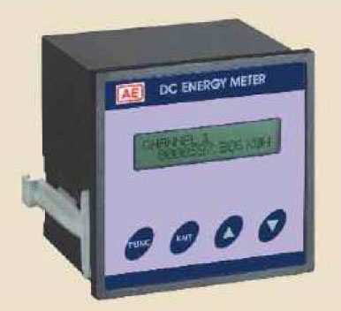
Description / Specification of Dc Energy Meter
We are involved in offering a wide range of Dc Energy Meter to our most valued clients. Our range of these are widely appreciated by our clients which are situated all round the nation. We offer our range of it at most affordable prices.
We introduce ourselves as an eminent trader and supplier of an extensive array of Dc Energy Meter. Prior to dispatch, our quality controllers run numerous tests on the entire range on various parameters of quality and durability. The offered equipment is manufactured using superior quality components with the aid of sophisticated techniques at the vendors' end. Moreover, our precious clients can purchase it in different technical specifications at reasonable price from us within promised time frame.
Features:
Sturdy design
Highly durable
Application specific design
Description / Specification of Digital Energy Meter (Counter Type)
We are involved in offering a wide range of Digital Energy Meter (Counter Type) to our most valued clients. Our range of these are widely appreciated by our clients which are situated all round the nation. We offer our range of it at most affordable prices.
We introduce ourselves as an eminent trader and supplier of an extensive array of Digital Energy Meter (Counter Type). Prior to dispatch, our quality controllers run numerous tests on the entire range on various parameters of quality and durability. The offered equipment is manufactured using superior quality components with the aid of sophisticated techniques at the vendors' end. Moreover, our precious clients can purchase it in different technical specifications at reasonable price from us within promised time frame.
Features:
Sturdy design
Highly durable
Application specific design
Description / Specification of Digital Energy Meter (Led Display And Rs 485 Interface)
We are involved in offering a wide range of Digital Energy Meter (Led Display And Rs 485 Interface) to our most valued clients. Our range of these are widely appreciated by our clients which are situated all round the nation. We offer our range of it at most affordable prices.
We introduce ourselves as an eminent trader and supplier of an extensive array of Digital Energy Meter (Led Display And Rs 485 Interface). Prior to dispatch, our quality controllers run numerous tests on the entire range on various parameters of quality and durability. The offered equipment is manufactured using superior quality components with the aid of sophisticated techniques at the vendors' end. Moreover, our precious clients can purchase it in different technical specifications at reasonable price from us within promised time frame.
Features:
Sturdy design
Highly durable
Application specific design
DESCRIPTION | |
It is used to measure the applied frequency, functionally similar to vibrating reed meter. The meter incorporates light emitting diodes LEDs which are used instead of vibrating reeds to indicate applied frequency. The frequency is determined by blinking LEDs. When applied frequency matches with the frequency marked on the dial, that particular LED blinks with maximum intensity. When the applied frequency is mid way between two adjacent LEDs, both LEDs blink. When the meter is switched on all the LEDs glow sequentially for a period of 1 to 1.5 seconds, thereafter it will indicate the applied frequency. |
|
All voltage ranges are available in single meter. Terminal screws with washers are provided only for specific voltage as per requirement & remaining two terminals are covered with insulated caps. |
FEATURES | |
• | No vibrating parts. |
• | No aging effect. |
• | Faster response. |
• | Lighter in weight. |
• | Low power consumption |
• | No effect of external vibration |
• | Visible in dark & from distance. |
ELECTRICAL SPECIFICATIONS | ||
• | TYPE | ELECTRONIC |
• | OPERATING VOLTAGE | 110V~125V, 220V-250V, 380V~440V. |
• | POWER CONSUMPTION | Less than 3VA (Single scale), Less than 6VA (Double scale). |
• | MEASURING METHOD | Time measurement between consecutive cycles. |
• | DISPLAY | Box LED, Colour Red/Green, Size 6.3 X 3.7mm |
• | SAMPLING RATE | 2-3 samples/sec. |
• | RESPONSE TIME | Less than 1 sec. |
• | INSULATION RESISTANCE | Greater than 20 Mohms at 500V DC. |
• | DIELECTRIC STRENGTH | 2kV RMS for 1 minute. |
• | OPERATING TEMP. | -10°C to 55°C |
• | STORAGE TEMP. | -20°C to 70°C |
• | HUMIDITY | Upto 95% RH |
• | CONFORMS TO | I.S. 1248 / B.S. 89. / I.E.C. 51. (Part - 4) |
AVAILABLE RANGES | ||||||||
MODEL | ELFS 72 | ELFS 96 | ELFS 96 | ELFS 144 | ELFS144 | |||
RANGE | Resolution | LEDS | Acc. # |
Single Scale | Single Scale | Double Scale | Single Scale | Double Scale |
45 -50 -55 | * | 13 | ±1 | |||||
47 - 50 -53 | 0.5Hz | 13 | ±1 | |||||
55 - 60 - 65 | * | 13 | ±1 | |||||
57 - 60 - 63 | 0.5Hz | 13 | ±1 | |||||
370-400-430 | 5Hz | 13 | ±1 | |||||
45 - 50 - 55 | 0.5Hz | 21 | ±1 | -- | -- | |||
48 - 50 - 52 | 0.2Hz | 21 | ±0.5 | -- | -- | |||
55- 60 - 65 | 0.5Hz | 21 | ±1 | -- | -- | |||
58 - 60 - 62 | 0.2Hz | 21 | ±0.5 | -- | -- | |||
380-400-420 | 2Hz | 21 | ±0.5 | -- | -- |
# % of center frequency Available models |
* There are 11LEDs in a row in steps of 1Hz for range (45-50-55Hz)/(55 - 60 - 65Hz) with additional 2 LEDs for (49.5 and 50.5Hz) / (59.5 and 60.5Hz) respectively. |
NOTE : Frequency Meter For Other Range / Resolution Shall Be Supplied on Request If Feasible |
MECHANICAL SPECIFICATIONS | |||||
MODEL | ELFS 72 | ELFS 96 | ELFD 96 | ELFS 144 | ELFD 144 |
SIZE (mm) | 72 x 72 x 70 | 96 x 96 x 70 | 96 x 96 x 70 | 144 x 144 x 60 | 144 x 144 x 60 |
PANEL CUTOUT (mm) | 60 x 60+0.7 | 92 x 92 +0.8 | 92 x 92 +0.8 | 138 x 138+1.0 | 138 x 138+1.0 |
WEIGHT (Approx.) | 350gms. | 400gms. | 600gms. | 500gms. | 700gms. |
TERMINAL ARRANGEMENT | |
ELFS 72 | ELFS 96 / ELFD 96 |
ELFS 144 | ELFD 144 |
Ordering information |
1) Type 2) Model 3) Range 4) Operating Voltage |
DESCRIPTION | ||
It is used to measure the applied frequency. Vibrating Reed Frequency meters indicate the supply frequency by means of individual reeds, when rated voltage ± 20% is applied across the terminals of the meter, the particular reed, whose natural frequency of vibration coincides with the supply frequency, vibrates with full amplitude. In case the supply frequency falls midway between two reeds both the reeds vibrate, at reduced amplitude. The amplitude of vibration at the tip of reeds is high enough for a distinct indication. |
FEATURES | |
• | Vibrating reed. |
• | No aging effect. |
• | Faster response. |
• | Lighter in weight. |
• | Low power consumption |
• | Rugged construction |
• | High reliability |
ELECTRICAL SPECIFICATIONS | ||
• | TYPE | Vibrating Reed |
• | OPERATING VOLTAGE | 110V~125V, 220V~250V, 380V~440V. |
• | POWER CONSUMPTION | Less than 0.3VA,0.6VA and 1.2VA for respective operating voltage in 72 & 96. 26 Sizes |
Less than 0.6VA, 1.2VA, 2.4VA for respective operating voltage in 144 size. | ||
• | DIELECTRIC STRENGTH | 2kV RMS for 1 minute. |
• | OPERATING TEMP. | -10°C to 55°C |
• | STORAGE TEMP. | -20°C to 70°C |
• | HUMIDITY | Upto 95% RH |
• | CONFORMS TO | I.S.1248 / I.E.C. 60051(Part4). |
AVAILABLE RANGES | ||||||||
MODEL | RFS 72 | RFS 96 | RFS96 | RFS 144 | RFS 144 | |||
RANGE | Resolution | Reeds | Acc.# | Single Scale | Single Scale | Dual Scale | Single Scale | Dual Scale |
45 - 50 - 55 | * | 13 | ±1 | |||||
47 - 50 - 53 | 0.5Hz | 13 | ±1 | |||||
55 - 60 - 65 | * | 13 | ±1 | |||||
57 - 60 - 63 | 0.5Hz | 13 | ±1 | |||||
45 - 50 - 55 | 0.5Hz | 21 | ±1 | -- | -- | -- | ||
55 - 60 -65 | 0.5Hz | 21 | ±1 | -- | -- | -- |
# % of centre frequency Available models | |
* | There are 11 reeds in a row in setps of 1Hz for range 45 - 50 - 55Hz (55 - 60 - 65Hz) with additional 2reeds for 49.5 and 50.5Hz (59.5 and 60.5Hz) respectively. |
MECHANICAL SPECIFICATIONS | |||||
MODEL | RFS 72 | RFS 96 | RFD 96 | RFS144 | RFD 144 |
SIZE (mm) | 72 x 72 x 70 | 96 x 96 x 70 | 96 x 96 x 70 | 144 x 144 x 60 | 144 x 144 x 60 |
PANEL CUTOUT (mm) | 68 x 68+0.7 | 92 x 92+0.8 | 92 x 92+0.8 | 138 x 138+1.0 | 138 x 138+1.0 |
WEIGHT (Approx.) | 300gms. | 360gms. | 550gms. | 650gms. | 950gms. |
RFS 72 | RFS 96 / RFD 96 |
RFS144 | RFD 144 |
Ordering information :1) Type 2) Operating Voltages 3) Model 4) Range |
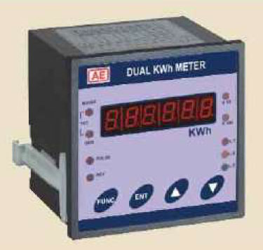
Description / Specification of Dual Kwh Meter
We are involved in offering a wide range of Dual Kwh Meter to our most valued clients. Our range of these are widely appreciated by our clients which are situated all round the nation. We offer our range of it at most affordable prices.
We introduce ourselves as an eminent trader and supplier of an extensive array of Dual Kwh Meter. Prior to dispatch, our quality controllers run numerous tests on the entire range on various parameters of quality and durability. The offered equipment is manufactured using superior quality components with the aid of sophisticated techniques at the vendors' end. Moreover, our precious clients can purchase it in different technical specifications at reasonable price from us within promised time frame.
Features:
Sturdy design
Highly durable
Application specific design
Description / Specification of Maximum Demand Controller Mdc 1000
We are involved in offering a wide range of Maximum Demand Controller Mdc 1000 to our most valued clients. Our range of these are widely appreciated by our clients which are situated all round the nation. We offer our range of it at most affordable prices.
We introduce ourselves as an eminent trader and supplier of an extensive array of Maximum Demand Controller Mdc 1000. Prior to dispatch, our quality controllers run numerous tests on the entire range on various parameters of quality and durability. The offered equipment is manufactured using superior quality components with the aid of sophisticated techniques at the vendors' end. Moreover, our precious clients can purchase it in different technical specifications at reasonable price from us within promised time frame.
Features:
Sturdy design
Highly durable
Application specific design
DESCRIPTION |
It is a rotating disc type instrument. The disc rotates in clockwise direction when correctly connected to incoming three phase power supply. Black arrow on white disk indicates correct phase sequence. If rotation is anti-clockwise then it indicates that one of the phases is reversed. It is suitable for use only in horizontal position and should not be left in circuit. Three, 1 meter long red, yellow, blue colour leads with clips and sheaths are provided. |
ELECTRICAL SPECIFICATIONS | ||
• | TYPE | Electro-mechanical |
• | OPERATING VOLTAGE | 50V to 500V AC |
• | FREQUENCY | 25 Hz to 60 Hz. |
• | INSULATON RESISTANCE | Greater than 20 Mohms at 500V DC |
• | DIELECTRIC STRENGTH | 2kV RMS for one minute |
• | OPERATING TEMP. | -10°C to 55°C |
• | STORAGE TEMP. | -20° to 70°C |
• | HUMIDITY | upto 95% RH |
MECHANICAL SPECIFICATIONS | ||
• | MODEL | PSI 96 M |
• | SIZE | 96 X 96 X 56mm (Supplied With carry bag) |
• | WEIGHT (Appro.) | 600gms |
Ordering information 1) Type 2) Model |
DESCRIPTION |
Protable Moving Coil DC, Moving Coil Rectifier type AC, Moving Iron AC ammeters & voltmeters and can be used in conjunction with transducers for measurement of frequency, power factor and low power factor wattage. Single phase dynamometric instrument is used for measurement of power at Unity Power Factor (UPF). |
FEATURES / ADVANTAGES | |
• | Instruments with accuracy class 1.0, 1.5. |
• | Instruments with multiple scale (refer table). |
• | Robust housing suitable for schools, workshops, field operations, for continuous use. |
ELECTRICAL SPECIFICATIONS | ||||
MODEL | TYPE | SCALE | RANGE | ACCURACY |
PORT- MSMB-1 |
MOVING IRON AC VOLT - AMMETER |
Quadruple | 0 - 62.5/125/250/500V & 0 - 2.5/5/10/25A or 0-75/150/300/600V & 0-1/3/10/30A |
1% |
PORT-MSMB-2 |
MOVING COIL DC VOLT-AMMETER |
Quadruple | 0 - 0.075/15/150/600V & 0 - 1.5/15/75/150A (with 75mV shunt) |
1.5% |
PORT MSMB-3 |
MOVING COIL DC & AC VOLTMETE |
Quadruple | 0 - 1.5/15/150/600V DC 0 - 6/60/300/600V AC |
1.5% |
FREQUENCY METER | Single | 45-55Hz or 55-65Hz or 380-420Hz at Single Voltage 62.5/10V/220/440V |
1% | |
POWER FACTOR METER 1 - Phase |
Single | 0.5 Lag - Unity - 0.5 Lead or 0.3 Lag-Unity-0.3Lead at Single Voltage 110V/220V/440V & Single Current 1A/5A |
2° | |
POWER FACTOR METER 3-Phase - 1Element |
Single | 0.5 Lag-Unity-0.5 Lead or 0.3 Lag-Unity-0.3 Lead at Single Voltage 110V/220V/440V & Single Current 1A/5A |
2° | |
LPF WATTMETER 1 Phase |
Dual | 62.5V/ 125V to 300V/600V & 50mA/100mA to 5A/10A | 0.5% |
MODEL | TYPE | *POTENTIAL COIL (A) | CURRENT COIL (A) | ACCURACY | |
PORT-MSMB-4 |
WATT METER 1Ph UPF |
SPSC | 75, 150, 300, 600 | 0.5, 1, 2, 2.5, 5, 10, 20 | 1.0% |
DPSC | 75/150, 150/300, 300/600 | ||||
TPSC | 75/150/300, 150/300/600 | ||||
SPDC | 75, 150, 300, 600 | 0.5/1, 1/2, 2.5/5, 5/10, 10/20 | |||
DPDC | 75/150, 150/300, 300/600 | ||||
TPDC | 75/150/300, 150/300/600 |
* 62.5/ 125/ 250/ 500V INSTEAD OF 75 / 150 / 300/ 600 V - ON REQUEST. |
Mechanical Specification | |
SIZE | HOUSING MATERIAL |
MODEL IDENTIFICATION |
SCALE | WEIGHT kg. (Appro.) |
|||
LENGTH mm |
WIDTH mm |
HEIGHT mm |
LENGHT mm (Appro.) |
DIVISIONS | |||
240 | 185 | 120 | Bakelite | MSMB- | 150 | 80 ~ 120 | 3 |
Ordering information |
Ammeter / Voltmeter |
1) Type 2) Model 3) Range 4) Scale 5) Accuracy |
Frequency Meter |
1) Type 2) Model 3) Range 4) Voltage 5) Accuracy |
Watt / PF Meter |
1) Type 2) Model, Parameter, Phase & Range 3) Operating Voltage & PTR 4) Operating Current & CTR. |
DESCRIPTION | |
'AE' SYNCHROSCOPE is categorized into two types A) Electro-mechanical and B) Electronic. |
ELECTRO-MECHANICAL TYPE |
It incorporates a POINTER and LED to indicate synchronising condition. If the generator- (II) frequency is higher or lower than that of mains- (I) the pointer rotates in clockwise or anti-clockwise direction respectively. The speed and direction of rotation depends upon difference in frequencies, which guides the operator to speed-up or slow-down the generator. Synchronising condition is determined by dark lamp method, wherein the pointer coincides with synchronising mark and the LED does not glow. The LED glows in accordance with difference in phase, frequency and amplitude of voltages. When the pointer is towards the bright LED, it indicates the antiphase condition. |
FEATURES | |
• | Rugged construction. |
• | Easy serviceability. |
• | Wide operating voltage range. |
ELECTRICAL SPECIFICATIONS | ||
• | TYPE | Electro-mechanical |
• | VOLTAGE AT SYNCHRONISM | 110V ± 2% |
• | OPERATING VOLTAGE | 110V ± 20% (for other voltages use separate PT box.) |
• | FREQUENCY | 50 / 60Hz ± 5% |
• | SYNCHRONISING CONDITION | Dark lamp method |
• | ACCURACY | 2° |
• | ANGLE OF ROTATION | 360° |
• | POWER CONSUMPTION | 3 VA for MAINS - (I) & 6VA for GENERATOR - (II) |
• | INSULATION RESISTANCE | Greater than 20 Mohms at 500V. DC. |
• | DIELECTRIC TEST | 2kV RMS for One minute |
• | OPERATING TEMP. | -10°C to 55°C |
• | STORAGE TEMP. | -20°C to 70°C |
• | HUMIDITY | Upto 95% RH |
• | INDICATION | Moving pointer & LED |
• | CONFORMS TO | I.S. 1248 / I.E.C. 51 (Part-5) |
MECHANICAL SPECIFICATIONS | |||
• | MODEL | SYN96M | SYN144M |
• | SIZE | 96 x 96 x 85mm | 144 x 144 x 60 mm |
• | PAN EL CUTOUT | 92 x 92+0.8mm | 138 x 138+1.0mm |
• | WEIGHT (Appro.) | Approx.750gms. | 1 kg. |
CAUTION : The meter is not to be left in circuit after synchronising. |
ELETRONIC TYPE |
It incorporates circle of LEDs which glows sequentially in either clockwise or anti-clockwise direction at variable speed in accordance with difference in frequencies of mains & generator. Synchronising condition is indicated by the glowing LED of "SYNCHRO ON" position. Antiphase condition is indicated by glowing LED of "SYNCHRO OFF" position at the bottom. This LED glows under following conditions |
1) Absence of mains-(l) and presence of generator voltage-(ll) |
2) If generator - (Il) voltage crosses ± 20% When frequencies of both supplies are equal, phase angle between two voltages is indicated by glowing of LED at an approximate angle with respect to "SYNCHRO ON" position. |
FEATURES | |
• | Continuous operation. |
• | No moving parts. |
• | Low power consumption. |
• | Visible in dark. |
ELECTRICAL SPECIFICATIONS | ||
• | TYPE | Electronic |
• | VOLTAGE AT SYNCHRONISM | 110V ± 2% |
• | OPERATING VOLTAGE | 110V ± 20% (for other voltages use separate PT box.) |
• | FREQUENCY | 50/60Hz ± 5% |
• | SYNCHRONISING CONDITION | Glowing of "SYNCHRO ON" LED |
• | ACCURACY | 2° |
• | ANGLE OF ROTATION | 360° |
• | POWER CONSUMPTION | 2VA for MAINS - (I) & 0.25VA for GENERATOR - (II) |
• | INSULATION RESISTANCE | Greater than 20 Mohms at 500V. DC. |
• | DIELECTRIC TEST | 2kV RMS for One minute |
• | OPERATING TEMP. | -10°C to 55°C |
• | STORAGE TEMP. | -20°C to 70°C |
• | HUMIDITY | Upto 95% RH |
• | INDICATION | Rotating LED |
• | CONFORMS TO | I.S. 1248 / I.E.C. 51 (Part-5) |
MECHANICAL SPECIFICATIONS | |||
• | MODEL | SYN 96 E | SYN 144 E |
• | SIZE | 96 x 96 x 75mm | 144 x 144 x 60 mm |
• | PAN EL CUTOUT | 92 x 92+0.8mm | 138 x 138+1.0mm |
• | WEIGHT(Appro.) | 450gms. | 650 gms. |
Ordering information 1) Type 2) Model 3) Operating voltage 4) Frequency |
DESCRIPTION | |
Moving coil instruments with circular scale of 240° employ a platinum taut band for suspension of moving coil assembly instead of pivot & jewel system. It is less prone to sluggishness & zero shift due to frictionless movement. These meters are basically used for the measurement of DC current & voltage, and can be used with built in rectifier for the measurement of AC current & voltage in the frequency range 45~65Hz. / 400Hz. The meters measure average value. It can be scaled to indicate RMS values (on request). These instruments are not recommended for non-sinusoidal waveforms of current & voltage. The other indications like Frequency, Power & Power factor can be offered with suitable external transducers. Speed indication is possible if used with AC tacho-generator (not in the scope of AE). |
FEATURES | |
• | Long scale instruments. |
ELECTRICAL SPECIFICATIONS | ||
• | TYPE | MOVING COIL 240°. |
• | OPERATING VOLTAGE | 60mV to 600V. |
• | OPERATING CURRENT | 500µA to 30A & Above 30A with external shunt. |
• | ACCURACY CLASS | 2.5 for SQ48, 1.5 for SQ72 & SQ96, 1.0 for SQ14 4, SQ110. |
• | DIELECTRIC TEST | 2kV RMS for 1 min. |
• | OPERATING TEMP. | -10°C to 55°C |
• | STORAGE TEMP. | -20°C to 70°C |
• | HUMIDITY | Up to 95% RH |
• | CONFORMS TO | I.S. 1248 / I.E.C. 60051 (Part 2) |
MODEL | SQ 48 | SQ 72 | SQ 96 | SQ 144 | SQ 110 |
ACCURACY CLASS | 2.5 | 1.5A | 1.0A | 1.0A | 1.0A |
D.C.AMMETER (MIN.) | 0-500µA | ||||
(MAX.) | 0-100mAB | 0 - 30AC | |||
D.C.VOLTMETER (MIN.) | 0 - 60mV | ||||
(MAX.) | 0-150mVB | 0 - 600V | |||
A.C.AMMETER (MIN.) | 0-10mAB | 0 - 10mA | |||
(MAX.) | 0-30AB | 0 - 30A | |||
A.C.VOLTMETER (MIN.) | 0-10VB | 0 - 10V | |||
(MAX.) | 0-600VB | 0 - 600V | |||
FREQ. METER | POSSIBLEB | 40Hz TO 100Hz AT 110V ~ 440V | |||
WATT / VAR METER | POSSIBLEB | POSSIBLED | 1PH, 3PH-2 / 3E :110V~440V,1A/5A | POSSIBLEE | |
VA METER | POSSIBLEB | POSSIBLED | 3PH-2 / 3E : 110V~440V, 1A/5A | POSSIBLEE | |
PF METER | POSSIBLEB | POSSIBLED | 1PH, 3PH-1E : 110V~ 440V, 1A / 5A |
Note : Range below minimum & above maximum on request if feasible. | ||
A | Accuracy Class 0.5 for all Frequency meters, 1.5 for SQ96,SQ144,SQ110, AC Ammeter, AC / Ammeter / Voltmeter & Power meter, 2° for all Power Factor meter, |
|
B | SQ48 - i) DC / AC Voltmeter, AC Ammeter with external box. ii) Frequency meter, Power meter with external transducer box. | |
C | For higher ranges use AE external shunts. (Refer Data Sheet for Shunts). | |
D | SQ72 - Power & Power factor meter with external transducer box. | |
E | SQ 110-Power meter with external transducer box. |
MECHANICAL SPECIFICATIONS | ||||||
MODEL | SQ 48 | SQ 72 | SQ 96 | SQ 144 | SQ 110 | |
FLANGE (mm) | 48 x 48 | 72 x 72 | 96 x 96 | 144 x 144 | 110 x 110 | |
PANEL CUTOUT(mm) | 45 x 45+0.6 | 68 x 68+0.7 | 92 x 92+0.8 | 138 x 138+1.0 | 100 Ø, 5 Ø, 4 holes 90x90 |
|
DEPTH (mm) |
DC | 55 | 55 | 55 | 60 | 100 |
AC | 55 | 75 | 75A | 60A | 100 | |
SCALE LENGTH (mm)(Appro.) | 70 - 75 | 105 -110 | 150 - 155 | 225 - 230 | 175 - 180 | |
WEIGHT (gms.) (Appro.) |
DC | 200 | 250 | 300 | 500 | 450 |
AC | 200 | 350 | 400B | 600B | 650 |
A | Depth 100mm for SQ96 & SQ144 Power meter. |
B | Weight 1.2kg for SQ96 Power meter, 1.5kg for SQ144 Power meter. |
Ordering information | ||
For all Models | 1) Type 2) Model 3) Range | |
Additional information for power and power factor measurments. |
4) frequency 5) Operating Voltage 6) Operating Current 7) PTR 8) CTR. |
DESCRIPTION | |
Moving Coil Instruments are protected from damage or breakage under adverse conditions due to spring loaded jewel & pivot system. These Instruments are free from external magnetic field influences because of centre magnet system and are "CE" certified. |
|
Ammeters with internal shunts are available upto 30 Amps and for higher currents upto 12000 Amps use external shunts of 50mV, 60mV, 75mV etc. (Please refer data sheet no. Shunt 03/99.) |
FEATURES | ||
• | SCALE | Linear. |
• | SCALE COLOUR | Special colour scales & marks for different ranges, (on request). |
• | GLASS | Anti-glare, (on request). |
• | HOUSING | Engineering plastic. |
• | TERMINAL PROTECTION | Shrouded terminals to protect from accident, (on request). |
ELECTRICAL SPECIFICATIONS | ||
• | TYPE | Moving Coil Slide in scale. |
• | OPERATING VOLTAGE | 50mV to 600V. |
• | OPERATING CURRENT | l00nA to 30A. & Above 30A external shunt. |
• | ACCURACY | Class 1.5. |
• | DIELECTRIC TEST | 2kV RMS for 1 min. |
• | OVERLOAD CONTINUOUS | 1.2 times. |
• | OVERLOAD SHORT TIME | 2 times VN / 10 times IN for 5 seconds. |
• | OPERATING TEMP. | -10°C to 55°C. |
• | STORAGE TEMP. | -20°C to 70°C. |
• | HUMIDITY | up to 95% RH |
• | CONFORMS TO | I.S. 1248 / I.E.C. 60051 (Part 2). |
Mechanical Specifications | ||
MODEL | SMC 72 | SMC 96 |
SIZE (mm) | 72 x 72 x 60 | 96 x 96 x 60 |
PANEL CUTOUT (mm) | 68 x 68 +0.7 | 92 x 92 +0.8 |
SCALE LENGTH (mm) (Appro.) | 60 | 90 |
WEIGHT ( gms.) (Appro.) | 130 | 190 |
Note : METERS ARE ALSO AVAILABLE IN 48x48x45 (SMC 48) & 144 x 144 x 60 (SMC 144) IN NON SLIDE IN DIAL VERSION. |
MODEL | SMC 48 | SMC 144 |
SIZE (mm) | 48 x 48 x 45 | 144 x 144 x 50 |
PANEL CUTOUT (mm) | 45 x 45 + 0.7 | 138 x 138 +0.8 |
SCALE LENGTH (mm) (Appro.) | 40 | 145 |
WEIGHT ( gms.) (Approx.) | 100 | 400 |
Ordering information |
1) Type 2) Model 3) Operating Voltage / Current 4) mV in case of Ammeter with external shunt. |
DESCRIPTION | |
Moving Iron Instruments are protected from damage or breakage under adverse condition due to its spring loaded jewel & pivot system. These Instruments are free from external magnetic field influences because of magnetic shielding & are 'CE' certified. These instruments have a very efficient oil damping system, which gives almost a deadbeat movement to the pointer, without irksome oscillation. The movement is light yet sturdy and has a large torque to weight ratio which assures long life to instruments. |
|
These indicate true RMS values practically independent of waveform even of high harmonics. The scale is compressed initially. Readability starts from 10 to 15 degree approximately. |
FEATURES | ||
• | Scale | Non-linear. |
• | Suppression | Initial suppression for Voltmeter & End suppression upto 6 times for Ammeter. (on request) |
• | Scale Colour | Special colour scales and marks for different ranges, (on request). |
• | Housing | Engineering plastic. |
• | Terminal Protection | Shrouded terminals to protect from accident, (on request). |
• | Glass | Anti - glare. (on request) |
ELECTRICAL SPECIFICATIONS | ||
• | TYPE | Moving Iron Slide In Scale. |
• | OPERATING VOLTAGE (For Voltmeter) Burden |
15V to 600V. 100V / 110V for PT secondary. 15V to 30V - <100mA, 50V to 100V - < 30mA, 110V to 200V - <15mA, 200V to 600V - <7.5mA. |
• | OPERATING CURRENT (For Ammeter) Burden |
1 A to100A in 72x72, 1A to 200A in 96x96 1A / 5A for CT secondary. 0.25A to 30A - < 1VA, Above 30A - < 1.5 VA. |
• | FREQUENCY | 45 ~ 65Hz. (400Hz. on request). |
• | ACCURACY | Class 1.5 |
• | DIELECTRIC TEST | 2kV RMS or 1 minute. |
• | OVERLOAD CONTINUOUS | 1.2 times |
• | OVERLOAD SHORT TIME | 2 times VN / 10 times IN for 5 seconds. |
• | OPERATING TEMP. | -10°C to 55°C |
• | STORAGE TEMP. | -20°C to 70°C |
• | HUMIDITY | upto 95% RH |
• | CONFORMS TO | I.S. 1248 / I.E.C. 60051 (Part 2). |
MECHANICAL SPECIFICATIONS | ||
MODEL | SMI 72 (Slide in) | SMI 96 (Slide in) |
SIZE ( mm ) | 72 x 72 x 60 | 96 x 96 x 60 |
PANEL CUTOUT ( mm ) | 68 x 68 +0.7 | 92 x 92 +0.8 |
SCALE LENGTH ( Appro. mm ) | 60 | 90 |
WEIGHT ( Appro. gms. ) | <145 For 72 SQ Amps <180 For 72 SQ Volts |
<200 For 96 SQ Amps <230 For 96 SQ Volts |
Note : METERS ARE ALSO AVAILABLE IN 48x48x45 (SMI 48) & 144x144x60 (SMI 144) IN NON SLIDE IN DIAL VERSION. |
MODEL | SMI 48 | SMI 144 |
SIZE (mm) | 48 x 48 x 45 | 144 x 144 x 50 |
PANEL CUTOUT (mm) | 45 x 45 +0.6 | 138 x 138 +1.0 |
SCALE LENGTH (Appro. mm.) | 40 | 145 |
WEIGHT (Appro. gms.) | 100 | 400 |
Ordering information |
1) Type 2) Model 3) Operating Voltage & PTR Voltmeter 4) Operating Current & CTR For Ammeter. |
DESCRIPTION | |
Maximum Demand meter is used for monitoring thermal loading in Power Distribution systems, Networks, Machines etc. It indicates maximum loading current over a period. Short-period current peaks are not registered but long overloads are registered. |
FEATURES | |||||||
• | RMS measurement of maximum current. | • | 20% overload capacity. | ||||
• | Long current peaks are registered. | • | Instantaneous current measurement. | ||||
• | Red pointer to indicate maximum current reached. | • | Sturdy movement. | ||||
• | Analogue Indication. |
ELECTRICAL SPECIFICATIONS | ||||||||||||
• | TYPE | BIMETALLIC; ANALOGUE AMMETER. | ||||||||||
• | OPERATING CURRENT | 1 Amp or 5Amp | ||||||||||
• | FREQUENCY | 40 ~ 65Hz. | ||||||||||
• | ACCURACY | ± 3% for resettable red pointer (Bimetallic). | ||||||||||
± 1.5% instantaneous value pointer (Moving Iron) | ||||||||||||
• | THERMAL LAG (SETTING TIME) | 15 minutes (standard) & 8 minutes (on special request). | ||||||||||
• | VA BURDEN | Approx. 3.5VA for Bimetallic Ammeters & | ||||||||||
Approx. 4VA for Bimetallic And Moving Iron Ammeter. | ||||||||||||
• | INSULATION RESISTANCE | Greater than 20 Mohms at 500V DC | ||||||||||
• | DIELECTRIC TEST | 2kV rms for 1 minute. | ||||||||||
• | OPERATING TEMP. | -10°C to 55°C (for Analogue Instrument) | ||||||||||
• | STORAGE TEMP. | -20°C to 70°C | ||||||||||
• | HUMIDITY | upto 95% RH |
MECHANICAL SPECIFICATION | |||||
MODEL | MDIS 72 A | MDID 72A | MDIS 96A* | MDID 96A* | |
SIZE (mm) | 72 x72 x 70 | 72 x72 x 70 | 96 x 96 x70 | 96 x 96 x70 | |
PANEL CUTOUT (mm) | 68 x 68+0.7 | 68 x 68+0.7 | 92 x 92+0.8 | 92 x 92+0.8 | |
SCALE LENGTH (Approx.) OF BIMETALLIC SYSTEM |
60mm | 60mm | 90mm | 90mm | |
SCALE LENGTH (Approx.) OF MI SYSTEM | N.A. | 38mm | N.A. | 70mm | |
WEIGTH (Approx.) (gms) | 180 | 200 | 230 | 250 | |
* These models are available at present |
PRIMARY CURRENT |
SECONDARY CURRENT 5AMPS OR 1AMPS | |||||
-SCALE- | ||||||
MODEL | MDIS 72A | MDID 72A | MDIS 96A | MDID 96A | ||
100% | 120% | 120% | 200% | 120% | 120% | 200% |
10A | 12A | 12A | 0......... 10/20A | 12A | 12A | 0.................. 10/20A |
15A | 18A | 18A | 0......... 15/30A | 18A | 18A | 0.................. 15/30A |
20A | 24A | 24A | 0..........20/40A | 24A | 24A | 0...................20/40A |
25A | 30A | 30A | 0..........25/50A | 30A | 30A | 0...................25/50A |
30A | 36A | 36A | 0..........30/60A | 36A | 36A | 0...................30/60A |
40A | 48A | 48A | 0..........40/80A | 48A | 48A | 0...................40/80A |
50A | 60A | 60A | 0.........50/100A | 60A | 60A | 0.................50/100A |
60A | 72A | 72A | 0.........60/120A | 72A | 72A | 0.................60/120A |
75A | 90A | 90A | 0........75/150A | 90A | 90A | 0.................75/150A |
80A | 96A | 96A | 0.........80/160A | 96A | 96A | 0.................80/160A |
100A | 120A | 120A | 0.......100/200A | 120A | 120A | 0...............100/200A |
125A | 150A | 150A | 0.......125/250A | 150A | 150A | 0...............125/250A |
150A | 180A | 180A | 0.......150/300A | 180A | 180A | 0...............150/300A |
200A | 240A | 240A | 0.......200/400A | 240A | 240A | 0...............200/400A |
250A | 300A | 300A | 0.......250/500A | 300A | 300A | 0...............250/500A |
300A | 360A | 360A | 0......300/600A | 360A | 360A | 0...............300/600A |
400A | 480A | 480A | 0......400/800A | 480A | 480A | 0.................400/800 |
500A | 600A | 600A | 0.....500/1000A | 600A | 600A | 0.............500/1000A |
600A | 720A | 720A | 0.....600/1200A | 720A | 720A | 0.............600/1200A |
750A | 900A | 900A | 0.....750/1500A | 900A | 900A | 0.............750/1500A |
800A | 960A | 960A | 0.....800/1600A | 960A | 960A | 0.............800/1600A |
1000A | 1.2kA | 1.2kA | 0............1/2kA | 1.2kA | 1.2kA | 0....................1/2kA |
1200A | 1.4kA | 1.4kA | 0......1.2/2.4kA | 1.4kA | 1.4kA | 0...............1.2/2.4kA |
1500A | 1.8kA | 1.8kA | 0.........1.5/3kA | 1.8kA | 1.8kA | 0..................1.5/3kA |
2000A | 2.4kA | 2.4kA | 0............2/4kA | 2.4kA | 2.4kA | 0....................2/4kA |
2500A | 3.0kA | 3.0kA | 0.........2.5/5kA | 3.0kA | 3.0kA | 0.................2.5/5kA |
3000A | 3.6kA | 3.6kA | 0............3/6kA | 3.6kA | 3.6kA | 0....................3/6kA |
4000A | 4.8kA | 4.8kA | 0............4/8kA | 4.8kA | 4.8kA | 0....................4/8kA |
5000A | 6.0kA | 6.0kA | 0..........5/10kA | 6.0kA | 6.0kA | 0..................5/10kA |
Ordering information | |||||||
1) Type 2) Model 3) Operating Current 4) C.T.R. 5) Thermal lag / Setting Time |
Description / Specification of Multi Function Meter Ae90xx With Dg Monitor And Printer
We are involved in offering a wide range of Multi Function Meter Ae90xx With Dg Monitor And Printer to our most valued clients. Our range of these are widely appreciated by our clients which are situated all round the nation. We offer our range of it at most affordable prices.
We introduce ourselves as an eminent trader and supplier of an extensive array of Multi Function Meter Ae90xx With Dg Monitor And Printer. Prior to dispatch, our quality controllers run numerous tests on the entire range on various parameters of quality and durability. The offered equipment is manufactured using superior quality components with the aid of sophisticated techniques at the vendors' end. Moreover, our precious clients can purchase it in different technical specifications at reasonable price from us within promised time frame.
Features:
Sturdy design
Highly durable
Application specific design
Description / Specification of Multifunction Meter Ae9000 Ae9001 Ae9002 Ae9003 Part I
We are involved in offering a wide range of Multifunction Meter Ae9000 Ae9001 Ae9002 Ae9003 Part I to our most valued clients. Our range of these are widely appreciated by our clients which are situated all round the nation. We offer our range of it at most affordable prices.
We introduce ourselves as an eminent trader and supplier of an extensive array of Multifunction Meter Ae9000 Ae9001 Ae9002 Ae9003 Part I. Prior to dispatch, our quality controllers run numerous tests on the entire range on various parameters of quality and durability. The offered equipment is manufactured using superior quality components with the aid of sophisticated techniques at the vendors' end. Moreover, our precious clients can purchase it in different technical specifications at reasonable price from us within promised time frame.
Features:
Sturdy design
Highly durable
Application specific design
Description / Specification of Multifunction Meter Ae9000 Ae9001 Ae9002 Ae9003 Part Ii
We are involved in offering a wide range of Multifunction Meter Ae9000 Ae9001 Ae9002 Ae9003 Part Ii to our most valued clients. Our range of these are widely appreciated by our clients which are situated all round the nation. We offer our range of it at most affordable prices.
We introduce ourselves as an eminent trader and supplier of an extensive array of Multifunction Meter Ae9000 Ae9001 Ae9002 Ae9003 Part Ii. Prior to dispatch, our quality controllers run numerous tests on the entire range on various parameters of quality and durability. The offered equipment is manufactured using superior quality components with the aid of sophisticated techniques at the vendors' end. Moreover, our precious clients can purchase it in different technical specifications at reasonable price from us within promised time frame.
Features:
Sturdy design
Highly durable
Application specific design
Description / Specification of Multifunction Meter Ae9000 With Thd Measurement
We are involved in offering a wide range of Multifunction Meter Ae9000 With Thd Measurement to our most valued clients. Our range of these are widely appreciated by our clients which are situated all round the nation. We offer our range of it at most affordable prices.
We introduce ourselves as an eminent trader and supplier of an extensive array of Multifunction Meter Ae9000 With Thd Measurement. Prior to dispatch, our quality controllers run numerous tests on the entire range on various parameters of quality and durability. The offered equipment is manufactured using superior quality components with the aid of sophisticated techniques at the vendors' end. Moreover, our precious clients can purchase it in different technical specifications at reasonable price from us within promised time frame.
Features:
Sturdy design
Highly durable
Application specific design
DESCRIPTION |
Protable dynamometric types instruments, incorporating single element / two elements or three elements power measurement methods and specially designed to be operated in horizontal position. |
FEATURES / ADVANTAGES | |
• | Instruments with accuracy class 0.5 for 1 Ph Watt, 1.5 for 3Ph, 2° for PF. |
• | Instruments with multiple scale available (refer table). |
• | Robust housing suitable for schools, workshops and field operations for continuous use. |
ELECTRICAL SPECIFICATIONS | |||||
TYPE | MODEL | POTENTIAL COIL (A) | CURRENT COIL (A) | ACCURACY | |
Watt Meter With Low Power Factor |
PORT LSDW-1 |
TPDC | 75/150/300,150/300/600 | 0.5/1,1/2,2.5/5,5/10,10/20 | 1.5% |
WATT METER |
PORT LSDW-2 |
SPSC | 75,150,300,600 | 0.5,1,2,2.5,5,10,20 | 0.5% |
DPSC | 75/150,150/300,300/600 | ||||
TPSC | 75/150/300,150/300/600 | ||||
SPDC | 75,150,300,600 | 0.5/1,1/2,2.5/5,5/10,10/20 | |||
DPDC | 75/150,150/300,300/600 | ||||
TPDC | 75/150/300,150/300/600 | ||||
PORT LSDW-3 |
SPSC | 75,150,300,600 | 0.5,1,2,2.5,5,10,20 | 1.5% | |
PORT LSDW-4 |
SPSC | 75,150,300,600 | 0.5,1,2,2.5,5,10,20 | ||
DPDC | 75/150,150/300,300/600 | 0.5/1,1/2,2.5/5,5/10,10/20 | |||
PORT LSDW-5 |
SPSC | 75,150,300,600 | 0.5, 1, 2, 2.5, 5, 10, 20 | ||
SPDC | 0.5/1,1/2,2.5/5,5/10,10/20 | ||||
VAR METER |
PORT LSDW-6 |
SPSC | 75,150,300,600 | 0.5,1,2,2.5,5,10,20 | 1.5% |
DPDC | 75/150,150/300,300/600 | 0.5/1,1/2,2.5/5,5/10,10/20 | |||
PORT LSDW-7 |
SPSC | 75,150,300,600 | 0.5, 1, 2, 2.5, 5, 10, 20 | ||
SPDC | 0.5/1,1/2,2.5/5,5/10,10/20 | ||||
POWER FACTOR METER |
PORT LSDW-8 |
SPSC | 75,150,300,600 | 0.5,1,2,2.5,5,10,20 | 2° |
DPSC | 75/150,150/300,300/600 | ||||
TPSC | 75/150/300,150/300/600 | ||||
SPDC | 75,150,300,600 | 0.5/1,1/2,2.5/5,5/10,10/20 | |||
DPDC | 75/150,150/300,300/600 | ||||
TPDC | 75/150/300,150/300/600 | ||||
PORT LSDW-9 |
SPSC | 75,150,300,600 | 0.5,1,2,2.5,5,10,20 |
SELECTION OF RANGES |
Upper limit of measuring range for meters shall be one of the following values - |
1, 1.2, 1.5, 2, 2.5, 3, 4, 5, 6, 7.5, 8 or their decimal multiples. |
Example for selection of proper range |
1 ) Formula for 1 Phase active power |
P(max) = VI COS¢ Where COS¢ = 1. |
If Voltage = 500V & Current = 2.5A calculated power = 500 x 2.5 x 1 = 1.25kW. |
If the calculated value is 1.25kW 0 - 1.2kW or 0 - 1.25kW shall be selected as a range for power. |
2) Formula for 3 Phase active power with PT & CT. |
P(max) = √ 3VI COS¢ x PTR x CTR Where COS ¢ = 1. |
If Voltage = 110V & Current = 5A PTR = 400kV/110V CTR = 1000A/5A |
calculated power = √ 3 x 110x5 x (400x1000/110) x (1000/5)= 692MW. |
If the calculated value is 692MW 0 - 600MW or 0 - 750MW shall be selected as a range for power. |
Note : | |
• | All Wattmeters are calibrated at cos¢ = 1 and Varmeter at sin¢ = 1 |
• | All Low Power Factor Wattmeters are calibrated at cos¢ = 0.2 lag. |
• | Voltage & Current range other than specified can be supplied on request, if feasible. |
Mechanical Specifications | |
Fig. 1 | Fig. 2 |
SIZE | LENGTH mm |
WIDTH mm |
HEIGHT mm |
HOUSING MATERIAL |
MODEL IDENTIFICATION |
SCALE | WEIGHT kg. (Approx.) |
|
LENGHT mm (Approx.) |
DIVISIONS | |||||||
1 | 300 | 200 | 155/190 | Wooden Box | LSDW- | 150 | 100 ~ 150 | 4 ~ 5 |
2 | 225 | 355 | 190/225 | Wooden Box | LSDW- | 150 | 100 ~ 150 | 5.5 ~ 7.5 |
Ordering information |
1) Type 2) Model 3) Parameter, Phase, Range 3) Operating Voltage & PTR 4) Operating Current & CTR. |
DESCRIPTION |
Protable Moving Coil or Moving Coil rectifier type instruments or Dynamometric type of instruments, specially designed to be operated in horizontal position (also in inclined position upto 45°) & can be carried along safely. |
FEATURES / ADVANTAGES | |
• | Instruments with 0.5 accuracy class. |
• | Instruments with multiple scale available (refer table). |
• | Robust housing suitable for schools, workshops and field operations for continuous use. |
• | Precision instruments suitable for standard laboratories. |
ELECTRICAL SPECIFICATIONS | ||||
MODEL | TYPE | SCALE | RANGE | ACC. |
PORT LSPW-1 |
D.C. µ - AMMETER | Single | 500µA,1000µA | 0.5% |
Dual | 500µA / 1000µA | |||
D.C. MILLI-AMMETER | Single | 1mA, 2.5mA, 3mA, 5mA, 7.5mA, 10mA, 25mA, 30mA, 50mA, 75mA, 100mA, 250mA, 300mA, 500mA, 750mA, 1000mA |
||
Dual | 1/2mA, 2.5/5mA, 5/10mA, 10/20mA, 15/30mA, 25/50mA, 50/100mA, 150/300mA, 250/500mA. 500/1000mA. |
|||
D.C. AMMETER | Single | 1A,2.5A,3A,5A,10A,15A,20A,25A,30A | ||
Dual | 1/2A, 2.5/5A, 5/10A, 10/20A, 15/30A. | |||
D.C.MILLIVOLTMETER | Single | 25mV, 50mV, 75mV, 100mV, 150mV, 300mV, 500mV, 1000mV. |
||
Dual | 25/50mV, 50/100mV,75/150mV,100/200mV 150/300mV, 250/500mV, 500/1000mV. |
|||
Triple | 25/50/100mV, 50/100/200mV,75/150/300mV 150/300/600mV, 250/500/1000mV. |
|||
Quadruple | 25/50/100/200mV, 125/250/500/1000mV | |||
D.C. VOLTMETR | Single | 1V,2.5V,3V,5V,7.5V,10V,15V,20V,25V,30V, 50V,75V, 100V. 150V,200V,250V,300V,500V,600V,1000V. |
||
Dual | 1/2V, 2.5/5V, 5/10V, 30/60V, 50/100V, 75/150V, 100/200V, 150/300V,250/500V, 300/600V, 500/1000V. |
|||
Triple | 1.5/3/7.5V, 3/7.5/15V, 7.5/15/30V, 15/30/75V, 25/50/100V,75/150/300V, 125/250/500V, 150/300/600V |
|||
Quadruple | 1.5/3/7.5/15V, 3/7.5/15/30V, 7.5/15/30/60V, 15/30/75/150V, 30/75/150/300V, 75/150/300/600V. | |||
PORT LSPW-2 |
A.C. AMMETER | Single | 0.5A, 1A, 2.5A, 5A, 10A,15A,20A,30A | 0.5% |
Dual | 1/2A,2.5/5A,5/10A & also 0.2/1A, 0.5/2.5A, 1/5A,2/10A,10/20A,15/30A. |
|||
A.C. VOLTMETER | Single | 62.5V, 75V, 125V, 150V, 250V, 300V, 500V, 600V. | ||
Dual | 62.5/125V, 75/150V, 125/250V, 150/300V, 250/500V. 300/600V. |
|||
Triple | 62.5/125/250V, 75/150/300V,125/250/500V. 150/300/600V |
MECHANICAL CONSTRUCTION | |
SIZE | LENGTH mm |
WIDTH mm |
HEIGHT mm |
HOUSING MATERIAL |
MODEL IDENTIFICATION |
SCALE | WEIGHT kg. (Approx.) |
|
LENGTH mm (Approx.) |
DIVISION nos. |
|||||||
1 | 300 | 200 | 155 | Wooden Box | LSPW-1 | 150 | 100 ~ 150 | 4 |
2 | 300 | 200 | 190 | Wooden Box | LSPW-2 | 150 | 100 ~ 150 | 5 |
Ordering information |
1) Type 2) Model 3) Scale 4) Range 5) Accuracy |
DESCRIPTION |
Portable Moving Coil DC, Moving Coil rectifier type AC, Moving Iron AC ammeters & voltmeters suitable for use in schools, laboratories, workshops & for field operation. Specially designed to be operated in horizontal position (also in inclined position upto 45°) & can be carried along safely. |
FEATURES / ADVANTAGES | |
• | Instruments with accuracy class 1.0 for DC/AC, 1.5 for Rectifier type AC. |
• | Instruments with multiple scale (refer table). |
• | Robust housing suitable for schools, workshops and field operations for continuous use. |
ELECTRICAL SPECIFICATION | ||||
MODEL | TYPE | SCALE | RANGE | ACC. |
PORT MSSB-1 |
D.C.µ -Ammeter | Single | 50µA,100µA, 150µA,250µA,500µA,1000µA. | 1.0% |
Dual | 50/100µA, 100/200µA, 150/300µA, 250/ 500µA, 500/1000µA. | |||
D.C. MILLI-Ammeter |
Single | 1mA, 2.5mA, 3mA, 5mA, 7.5mA,10mA, 25mA, 30mA, 50mA, 75mA,100mA, 250mA, 300mA, 500mA, 750mA, 1000mA. |
||
Dual | 1/2mA, 2.5/5mA, 5/10mA,10/20mA,15/30mA, 25/50mA, 50/100mA,150/300mA, 250/500mA, 500/1000mA. |
|||
D.C.AMMETER | Single | 1A, 2.5A, 3A, 5A, 10A, 15A, 20A, 25A, 30A (INT.SHUNT). |
||
Dual | 1/2A, 2.5/5A, 5/10A, 10/20A,15/30A (INT.SHUNT). | |||
D.C. MILLIVOLTMETER | Single | 10mV, 25mV, 50mV, 75mV,100mV, 150mV, 300mV, 500mV,1000mV. |
||
Dual | 10/20mV, 25/50mV, 50/100mV, 75/150mV 100/200mV, 150/300mV, 250/500mV, 500/1000mV. |
|||
Triple | 25/50/100mV, 50/100/200mV, 75/150/300mV, 150/300/600mV, 250/500/1000mV. |
|||
Quadruple | 25/50/100/200mV, 125/250/500/1000mV. | |||
D.C. VOLTMETER | Single | 1V, 2.5V, 3V, 5V, 7.5V, 10V, 15V, 20V, 25V, 30V, 50V, 75V, 100V, 150V, 200V, 250V, 300V, 500V, 600V, 1000V. |
||
Dual | 1/2V, 2.5/5V, 5/10V, 30/60V, 50/100V, 75/150V, 100/200V, 150/300V, 250/500V, 300/600V, 500/1000V. |
|||
Triple | 1.5/3/7.5V, 3/7.5/15V, 7.5/15/30V, 15/30/75V, 25/50/100V, 75/150/300V, 125/250/500V, 150/300/600V, 250/500/1000V. |
|||
Quadruple | 1.5/3/7.5/15V, 3/7.5/15/30V, 7.5/15/30/60V, 15/30/75/150V, 30/75/150/300V, 75/150/300/600V, 125/250/500/1000V. |
|||
PORT MSSB-2 |
A.C. MILLI-AMMETER |
Single | 10mA, 50mA, 100mA, 250mA, 500mA, 1000mA. | 1.5% |
A.C .AMMETER | Single | 1A, 5A, 10A, 15A, 20A, 25A, 30A. | ||
A.C. VOLTMETER | Single | 3V, 7.5V, 10V, 15V, 20V, 25V, 50V, 100V, 150V, 300V, 600V. |
||
Dual | 7.5/15V, 10/20V, 15/30V, 25/50V, 50/100V, 150/300V, 300/600V. |
|||
Triple | 3/7.5/15V, 7.5/15/30V, 15/30/75V, 30/75/150V, 75/150/300V, 125/250/500V, 150/300/600V. |
|||
PORT MSSB-3 |
A.C.AMMETER | Single | 0.2A, 0.5A, 1A, 2.5A, 5A, 10A, 15A, 20A, 30A, 50A, 100A. |
1.0% |
Dual | 0.5/1A, 1/2A, 2.5/5A 5/10A & also 0.2/1A, 0.5/2.5A, 1/5A, 2/10A, 10/20A, 15/30A, 25/30A, 50/100A. | |||
Triple | 1/3/10A, 3/10/30A, 10/30/100A, 5/10/25A, 10/25/50A, 25/50/100A. | |||
Quadruple | 1/3/10/30A, 3/10/30/100A, 5/10/25/50A, 10/25/50/100A. |
|||
Quadruple | 1/3/10/30/100A, 5/10/25/50/100A | |||
A.C.VOLTMETER | Single | 15V, 30V, 62.5V, 75V, 125V, 150V, 250V, 300V, 500V, 600V. |
||
Dual | 15/30V, 30/60V, 62.5/125V, 75/150V, 125/250V, 150/300V, 250/500V, 300/600V. |
|||
Triple | 15/3075V, 62.5/125/250V, 75/150/300V, 125/250/500V, 150/300/600V. |
MECHANICAL CONSTRUCTION | |
Size | HOUSING MATERIAL |
MODEL IDENTIFICATION |
SCALE | WEIGHT kg. (Approx.) |
|||
LENGTH mm |
WIDTH mm |
HEIGHT mm |
LENGTH mm(Approx.) |
DIVISIONs | |||
240 | 185 | 80 | Bakelite | MSSB- | 150 | 80 ~ 120 | 2.5 |
Ordering information |
1) Type 2) Model 3) Scale 4) Range 5) Accuracy |
DESCRIPTION |
Portable Moving Coil DC, Moving Coil rectifier type AC, Moving Iron AC ammeters & voltmeters suitable for cartier replica use in schools, laboratories, workshops & for field operation. Specially designed to be operated in horizontal position (also in inclined position upto 45? & can be carried along safely. |
FEATURES | |
? | Instruments with accuracy class 1.0 for DC, 1.5 for AC. |
? | Instruments with multiple scale (refer table). |
? | Robust housing suitable for schools, workshops field operations, for continuous use. |
? | Instruments with high resistance to shock & vibrations. |
ELECTRICAL SPECIFICATIONS | ||||
MODEL | TYPE | SCALE | RANGE | ACC. |
PORT SSSP-1 |
D.C. µ-AMMETER |
Single | 250µA, 500µA, 1000µA | 1.0% |
Dual | 250µA, 500µA, 1000µA | |||
D.C. MILLI-AMMETER | Single | 1mA, 2.5mA, 3mA, 5mA, 7.5mA, 10mA, 25mA, 30mA, 50mA, 75mA, 100mA, 250mA, 300mA 500mA, 750mA, 1000mA |
||
Dual | 1/2mA, 2.5/5mA, 5/10mA, 10/20mA, 15/30mA, 25/50mA, 50/100mA, 150/300mA, 250/500mA. 500/1000mA. | |||
D.C. AMMETER | Single | 1A, 2.5A, 3A, 5A, 10A, 15A, 20A, 25A, 30A (INT.SHUNT) | ||
Dual | 1/2A, 2.5/5A, 5/10A, 10/20A, 15/30A. (INT. SHUNT) | |||
D.C.MILLI- VOLTMETER |
Single | 50mV, 75mv, 100mV, 150mV, 300mV, 500mV, 1000mV. |
||
Dual | 50/100/200mV, 75/150mV, 100/200mV, 150/300/600mV, 250/500/1000mV. |
|||
Triple | 50/100/200mV, 75/150/300mV, 150/300/600mV, 250/500/1000mV. |
|||
DC VOLTMETR | Single | 1V,2.5V,3V,5V,7.5V,10V,15V,20V,25V,30V,50V, 75V, 100V, 150V, 200V, 250V, 300V, 500V, 600V. |
||
Dual | 1/2V, 2.5/5V, 5/10V, 15/30V, 30/60V, 50/100V, 75/150V, 100/200V, 150/300V,250/500V, 300/600V. | |||
Triple | 1.5/3/7.5V, 15/30/75V, 25/50/100V,75/150/300V. 125/250/500V. 150/300/600V. | |||
PORT SSSP-2 |
A. C. MILLI-AMMETER | Single | 10mA, 50mA. | 1.5% |
A.C.VOLTMETER | Single | 10V, 15V, 20V, 25V, 50V, 100V, 150V, 300V, 600V. | ||
PORT SSSP-3 |
A.C.AMMETER | Single | 0.5A, 1A, 2.5A, 5A, 10A. | 1.5% |
Dual | 0.5/1 A. 1/2A. 2.5/5A. 5/10A. | |||
A.C.VOLTMETER | Single | 62.5V, 75V, 125V, 150V, 250V, 300V, 500V, 600V. | ||
Dual | 62.5/125V, 75/150V, 125/250V,150/300V. 250/500V. 300/600V. | |||
Triple | 62.5/125/250V, 75/150/300V, 125/250/500V, 150/300/600V. |
MECHANICAL CONSTRUCTION | |
Size | HOUSING mm |
MODEL mm |
SCALE | WEIGHT gm. (Approx.) |
|||
LENGTH mm |
WIDTH mm |
HEIGHT mm |
LENGTH mm (Approx.) |
DIVISIONS | |||
115 | 110 | 50 | Polycarbonate | SSSP- | 90 | 30 ~ 50 | 400 |
Ordering information |
1) Type 2) Model 3) Scale 4)Range 5) Accuracy |
DESCRIPTION |
Protable Moving Coil or Moving Coil rectifier type instruments or Dynamometric type of instruments, specially designed to be operated in horizontal position (also in inclined position upto 45°) & can be carried along safely. |
FEATURES / ADVANTAGES | |
• | Instruments with 0.5 accuracy class. |
• | Instruments with multiple scale available (refer table). |
• | Robust housing suitable for schools, workshops and field operations for continuous use. |
• | Precision instruments suitable for standard laboratories. |
ELECTRICAL SPECIFICATIONS | ||||
MODEL | TYPE | SCALE | RANGE | ACC. |
PORT LSPW-1 |
D.C. µ - AMMETER | Single | 500µA,1000µA | 0.5% |
Dual | 500µA / 1000µA | |||
D.C. MILLI-AMMETER | Single | 1mA, 2.5mA, 3mA, 5mA, 7.5mA, 10mA, 25mA, 30mA, 50mA, 75mA, 100mA, 250mA, 300mA, 500mA, 750mA, 1000mA |
||
Dual | 1/2mA, 2.5/5mA, 5/10mA, 10/20mA, 15/30mA, 25/50mA, 50/100mA, 150/300mA, 250/500mA. 500/1000mA. |
|||
D.C. AMMETER | Single | 1A,2.5A,3A,5A,10A,15A,20A,25A,30A | ||
Dual | 1/2A, 2.5/5A, 5/10A, 10/20A, 15/30A. | |||
D.C.MILLIVOLTMETER | Single | 25mV, 50mV, 75mV, 100mV, 150mV, 300mV, 500mV, 1000mV. |
||
Dual | 25/50mV, 50/100mV,75/150mV,100/200mV 150/300mV, 250/500mV, 500/1000mV. |
|||
Triple | 25/50/100mV, 50/100/200mV,75/150/300mV 150/300/600mV, 250/500/1000mV. |
|||
Quadruple | 25/50/100/200mV, 125/250/500/1000mV | |||
D.C. VOLTMETR | Single | 1V,2.5V,3V,5V,7.5V,10V,15V,20V,25V,30V, 50V,75V, 100V. 150V,200V,250V,300V,500V,600V,1000V. |
||
Dual | 1/2V, 2.5/5V, 5/10V, 30/60V, 50/100V, 75/150V, 100/200V, 150/300V,250/500V, 300/600V, 500/1000V. |
|||
Triple | 1.5/3/7.5V, 3/7.5/15V, 7.5/15/30V, 15/30/75V, 25/50/100V,75/150/300V, 125/250/500V, 150/300/600V |
|||
Quadruple | 1.5/3/7.5/15V, 3/7.5/15/30V, 7.5/15/30/60V, 15/30/75/150V, 30/75/150/300V, 75/150/300/600V. | |||
PORT LSPW-2 |
A.C. AMMETER | Single | 0.5A, 1A, 2.5A, 5A, 10A,15A,20A,30A | 0.5% |
Dual | 1/2A,2.5/5A,5/10A & also 0.2/1A, 0.5/2.5A, 1/5A,2/10A,10/20A,15/30A. |
|||
A.C. VOLTMETER | Single | 62.5V, 75V, 125V, 150V, 250V, 300V, 500V, 600V. | ||
Dual | 62.5/125V, 75/150V, 125/250V, 150/300V, 250/500V. 300/600V. |
|||
Triple | 62.5/125/250V, 75/150/300V,125/250/500V. 150/300/600V |
MECHANICAL CONSTRUCTION | |
SIZE | LENGTH mm |
WIDTH mm |
HEIGHT mm |
HOUSING MATERIAL |
MODEL IDENTIFICATION |
SCALE | WEIGHT kg. (Approx.) |
|
LENGTH mm (Approx.) |
DIVISION nos. |
|||||||
1 | 300 | 200 | 155 | Wooden Box | LSPW-1 | 150 | 100 ~ 150 | 4 |
2 | 300 | 200 | 190 | Wooden Box | LSPW-2 | 150 | 100 ~ 150 | 5 |
Ordering information |
1) Type 2) Model 3) Scale 4) Range 5) Accuracy |
DESCRIPTION |
Portable Moving Coil DC, Moving Coil rectifier type AC, Moving Iron AC ammeters & voltmeters suitable for use in schools, laboratories, workshops & for field operation. Specially designed to be operated in horizontal position (also in inclined position upto 45°) & can be carried along safely. |
FEATURES / ADVANTAGES | |
• | Instruments with accuracy class 1.0 for DC/AC, 1.5 for Rectifier type AC. |
• | Instruments with multiple scale (refer table). |
• | Robust housing suitable for schools, workshops and field operations for continuous use. |
ELECTRICAL SPECIFICATION | ||||
MODEL | TYPE | SCALE | RANGE | ACC. |
PORT MSSB-1 |
D.C.µ -Ammeter | Single | 50µA,100µA, 150µA,250µA,500µA,1000µA. | 1.0% |
Dual | 50/100µA, 100/200µA, 150/300µA, 250/ 500µA, 500/1000µA. | |||
D.C. MILLI-Ammeter |
Single | 1mA, 2.5mA, 3mA, 5mA, 7.5mA,10mA, 25mA, 30mA, 50mA, 75mA,100mA, 250mA, 300mA, 500mA, 750mA, 1000mA. |
||
Dual | 1/2mA, 2.5/5mA, 5/10mA,10/20mA,15/30mA, 25/50mA, 50/100mA,150/300mA, 250/500mA, 500/1000mA. |
|||
D.C.AMMETER | Single | 1A, 2.5A, 3A, 5A, 10A, 15A, 20A, 25A, 30A (INT.SHUNT). |
||
Dual | 1/2A, 2.5/5A, 5/10A, 10/20A,15/30A (INT.SHUNT). | |||
D.C. MILLIVOLTMETER | Single | 10mV, 25mV, 50mV, 75mV,100mV, 150mV, 300mV, 500mV,1000mV. |
||
Dual | 10/20mV, 25/50mV, 50/100mV, 75/150mV 100/200mV, 150/300mV, 250/500mV, 500/1000mV. |
|||
Triple | 25/50/100mV, 50/100/200mV, 75/150/300mV, 150/300/600mV, 250/500/1000mV. |
|||
Quadruple | 25/50/100/200mV, 125/250/500/1000mV. | |||
D.C. VOLTMETER | Single | 1V, 2.5V, 3V, 5V, 7.5V, 10V, 15V, 20V, 25V, 30V, 50V, 75V, 100V, 150V, 200V, 250V, 300V, 500V, 600V, 1000V. |
||
Dual | 1/2V, 2.5/5V, 5/10V, 30/60V, 50/100V, 75/150V, 100/200V, 150/300V, 250/500V, 300/600V, 500/1000V. |
|||
Triple | 1.5/3/7.5V, 3/7.5/15V, 7.5/15/30V, 15/30/75V, 25/50/100V, 75/150/300V, 125/250/500V, 150/300/600V, 250/500/1000V. |
|||
Quadruple | 1.5/3/7.5/15V, 3/7.5/15/30V, 7.5/15/30/60V, 15/30/75/150V, 30/75/150/300V, 75/150/300/600V, 125/250/500/1000V. |
|||
PORT MSSB-2 |
A.C. MILLI-AMMETER |
Single | 10mA, 50mA, 100mA, 250mA, 500mA, 1000mA. | 1.5% |
A.C .AMMETER | Single | 1A, 5A, 10A, 15A, 20A, 25A, 30A. | ||
A.C. VOLTMETER | Single | 3V, 7.5V, 10V, 15V, 20V, 25V, 50V, 100V, 150V, 300V, 600V. |
||
Dual | 7.5/15V, 10/20V, 15/30V, 25/50V, 50/100V, 150/300V, 300/600V. |
|||
Triple | 3/7.5/15V, 7.5/15/30V, 15/30/75V, 30/75/150V, 75/150/300V, 125/250/500V, 150/300/600V. |
|||
PORT MSSB-3 |
A.C.AMMETER | Single | 0.2A, 0.5A, 1A, 2.5A, 5A, 10A, 15A, 20A, 30A, 50A, 100A. |
1.0% |
Dual | 0.5/1A, 1/2A, 2.5/5A 5/10A & also 0.2/1A, 0.5/2.5A, 1/5A, 2/10A, 10/20A, 15/30A, 25/30A, 50/100A. | |||
Triple | 1/3/10A, 3/10/30A, 10/30/100A, 5/10/25A, 10/25/50A, 25/50/100A. | |||
Quadruple | 1/3/10/30A, 3/10/30/100A, 5/10/25/50A, 10/25/50/100A. |
|||
Quadruple | 1/3/10/30/100A, 5/10/25/50/100A | |||
A.C.VOLTMETER | Single | 15V, 30V, 62.5V, 75V, 125V, 150V, 250V, 300V, 500V, 600V. |
||
Dual | 15/30V, 30/60V, 62.5/125V, 75/150V, 125/250V, 150/300V, 250/500V, 300/600V. |
|||
Triple | 15/3075V, 62.5/125/250V, 75/150/300V, 125/250/500V, 150/300/600V. |
MECHANICAL CONSTRUCTION | |
Size | HOUSING MATERIAL |
MODEL IDENTIFICATION |
SCALE | WEIGHT kg. (Approx.) |
|||
LENGTH mm |
WIDTH mm |
HEIGHT mm |
LENGTH mm(Approx.) |
DIVISIONs | |||
240 | 185 | 80 | Bakelite | MSSB- | 150 | 80 ~ 120 | 2.5 |
Ordering information |
1) Type 2) Model 3) Scale 4) Range 5) Accuracy |
DESCRIPTION |
Portable Moving Coil DC, Moving Coil rectifier type AC, Moving Iron AC ammeters & voltmeters suitable for use in schools, laboratories, workshops & for field operation. Specially designed to be operated in horizontal position (also in inclined position upto 45°) & can be carried along safely. |
FEATURES | |
• | Instruments with accuracy class 1.0 for DC, 1.5 for AC. |
• | Instruments with multiple scale (refer table). |
• | Robust housing suitable for schools, workshops field operations, for continuous use. |
• | Instruments with high resistance to shock & vibrations. |
ELECTRICAL SPECIFICATIONS | ||||
MODEL | TYPE | SCALE | RANGE | ACC. |
PORT SSSP-1 |
D.C. µ-AMMETER |
Single | 250µA, 500µA, 1000µA | 1.0% |
Dual | 250µA, 500µA, 1000µA | |||
D.C. MILLI-AMMETER | Single | 1mA, 2.5mA, 3mA, 5mA, 7.5mA, 10mA, 25mA, 30mA, 50mA, 75mA, 100mA, 250mA, 300mA 500mA, 750mA, 1000mA |
||
Dual | 1/2mA, 2.5/5mA, 5/10mA, 10/20mA, 15/30mA, 25/50mA, 50/100mA, 150/300mA, 250/500mA. 500/1000mA. | |||
D.C. AMMETER | Single | 1A, 2.5A, 3A, 5A, 10A, 15A, 20A, 25A, 30A (INT.SHUNT) | ||
Dual | 1/2A, 2.5/5A, 5/10A, 10/20A, 15/30A. (INT. SHUNT) | |||
D.C.MILLI- VOLTMETER |
Single | 50mV, 75mv, 100mV, 150mV, 300mV, 500mV, 1000mV. |
||
Dual | 50/100/200mV, 75/150mV, 100/200mV, 150/300/600mV, 250/500/1000mV. |
|||
Triple | 50/100/200mV, 75/150/300mV, 150/300/600mV, 250/500/1000mV. |
|||
DC VOLTMETR | Single | 1V,2.5V,3V,5V,7.5V,10V,15V,20V,25V,30V,50V, 75V, 100V, 150V, 200V, 250V, 300V, 500V, 600V. |
||
Dual | 1/2V, 2.5/5V, 5/10V, 15/30V, 30/60V, 50/100V, 75/150V, 100/200V, 150/300V,250/500V, 300/600V. | |||
Triple | 1.5/3/7.5V, 15/30/75V, 25/50/100V,75/150/300V. 125/250/500V. 150/300/600V. | |||
PORT SSSP-2 |
A. C. MILLI-AMMETER | Single | 10mA, 50mA. | 1.5% |
A.C.VOLTMETER | Single | 10V, 15V, 20V, 25V, 50V, 100V, 150V, 300V, 600V. | ||
PORT SSSP-3 |
A.C.AMMETER | Single | 0.5A, 1A, 2.5A, 5A, 10A. | 1.5% |
Dual | 0.5/1 A. 1/2A. 2.5/5A. 5/10A. | |||
A.C.VOLTMETER | Single | 62.5V, 75V, 125V, 150V, 250V, 300V, 500V, 600V. | ||
Dual | 62.5/125V, 75/150V, 125/250V,150/300V. 250/500V. 300/600V. | |||
Triple | 62.5/125/250V, 75/150/300V, 125/250/500V, 150/300/600V. |
MECHANICAL CONSTRUCTION | |
Size | HOUSING mm |
MODEL mm |
SCALE | WEIGHT gm. (Approx.) |
|||
LENGTH mm |
WIDTH mm |
HEIGHT mm |
LENGTH mm (Approx.) |
DIVISIONS | |||
115 | 110 | 50 | Polycarbonate | SSSP- | 90 | 30 ~ 50 | 400 |
Ordering information |
1) Type 2) Model 3) Scale 4)Range 5) Accuracy |
Description / Specification of Built In Transducer Type Analogue Power Factor Meter
We are involved in offering a wide range of Built In Transducer Type Analogue Power Factor Meter to our most valued clients. Our range of these are widely appreciated by our clients which are situated all round the nation. We offer our range of it at most affordable prices.
We introduce ourselves as an eminent trader and supplier of an extensive array of Built In Transducer Type Analogue Power Factor Meter. Prior to dispatch, our quality controllers run numerous tests on the entire range on various parameters of quality and durability. The offered equipment is manufactured using superior quality components with the aid of sophisticated techniques at the vendors' end. Moreover, our precious clients can purchase it in different technical specifications at reasonable price from us within promised time frame.
Features:
Sturdy design
Highly durable
Application specific design
DESCRIPTION | ||
Dynamometric instruments are used for measurement of active, reactive & absolute power in 1 Phase & 3 Phase systems for balanced / unbalanced load conditions. Watt, Var & VA instruments incorporate current coils, connected in series with the load & pressure coils connected across the load. These instruments work on "Air cored Electro-Dynamometric" principle. |
FEATURES | ||
• | SCALE | Linear, Side zero or Center zero are available. |
• | HOUSING | Sheet Metal (Black painted). |
• | TERMINAL PROTECTION | Shrouded terminals to protect from accident, (on request). |
• | GLASS | Anti - glare (on request) |
ELECTRICAL SPECIFICATIONS | ||
• | TYPE | Dynamometric. |
• | OPERATING VOLTAGE | 75V to 500V for 1 Ph. 110V / 440V - PT secondary for 3Ph. |
BURDEN | <1.25VA upto 75V, <2.5VA - 100V to 150V, < 5VA - 200V to 300V, <10 VA - 350V to 600V |
|
• | OPERATING CURRENT | 0.5A to 10A for 1 Ph. 1A/5A-CT secondary for 3Ph |
BURDEN | <5VA upto 5A, <10VA upto 10A. | |
• | FREQUENCY | 45 ~ 65Hz. (400Hz. on request). |
• | ACCURACY | Class 1.5 for Watt / Var / VA. 2° for PF. |
• | DIELECTRIC TEST | 2kV RMS for 1 minute. |
• | OVERLOAD CONTINUOUS | 1.2 times |
• | OERLOAD SHORT TIME | 2 times VN / 10 times IN for 5 seconds. |
• | OPERATING TEMP. | -10°C to 55°C |
• | STORAGE TEMP. | -20°C to 70°C |
• | HUMIDITY | up to 95% RH |
• | CONFORMS TO | I.S. 1248 / I.E.C. 60051 (Part 3) for WATT / VAR & (Part 5) for PF. |
MECHANICAL SPECIFICATIONS | ||||
SIZE (mm) | DEPTH (mm) | PANEL CUTOUT (mm) | SCALE LENGTH (mm) | WEIGHT (gms.) |
96 x 96 1 ph or 3 ph | See table 1 | 92 x 92+0.8 | 80 (approx.) | See table 2 |
144 x 144 1ph or 3 ph | 138 x 138+1.0 | 140 (approx.) |
Table no. 1 (For Depth in mm) | ||||||||||||||||
Parameter | WATT METER | VAR METER | VA METER | PF METER | ||||||||||||
1PH | 3P1E | 3P2E | 3P3E | 1PH | 3P1E | 3P2E | 3P3E | 1PH | 3P1E | 3P2E | 3P3E | 1PH | 3P1E | 3P2E | 3P3E | |
96 x 96 | 80 | 80 | 100 | 100 | - | - | 100 | - | 80 | - | 100 | - | 80 | 80 | - | - |
144 x 144 | 85 | 85 | 125 | 165 | - | - | 125 | 165 | 85 | - | 125 | 165 | 125 | 125 | - | - |
Table no. 2 (For Weight in approx. kg) | ||||||||||||||||
Parameter | WATT METER | VAR METER | VA METER | PF METER | ||||||||||||
1PH | 3P1E | 3P2E | 3P3E | 1PH | 3P1E | 3P2E | 3P3E | 1PH | 3P1E | 3P2E | 3P3E | 1PH | 3P1E | 3P2E | 3P3E | |
96 x 96 | 0.5 | 0.5 | 0.7 | 0.7 | - | - | 0.7 | - | 0.5 | - | 0.8 | - | 0.6 | 0.7 | - | - |
144 x 144 | 1.0 | 1.0 | 1.4 | 1.7 | - | - | 1.4 | 1.8 | 1.8 | - | 1.5 | 1.8 | 1.2 | 1.4 | - | - |
Note : The connection diagram label is affixed on each meter. |
Ordering information |
1) Type 2) Size, 3) Parameter, 4) Phase & Element and Range 5) Operating Voltage & PTR 6) Operating Current & CTR. |
Description / Specification of Built In Transducer Type Digital Power Meter
We are involved in offering a wide range of Built In Transducer Type Digital Power Meter to our most valued clients. Our range of these are widely appreciated by our clients which are situated all round the nation. We offer our range of it at most affordable prices.
We introduce ourselves as an eminent trader and supplier of an extensive array of Built In Transducer Type Digital Power Meter. Prior to dispatch, our quality controllers run numerous tests on the entire range on various parameters of quality and durability. The offered equipment is manufactured using superior quality components with the aid of sophisticated techniques at the vendors' end. Moreover, our precious clients can purchase it in different technical specifications at reasonable price from us within promised time frame.
Features:
Sturdy design
Highly durable
Application specific design
DESCRIPTION |
Protable dynamometric types instruments, incorporating single element / two elements or three elements power measurement methods and specially designed to be operated in horizontal position. |
FEATURES / ADVANTAGES | |
• | Instruments with accuracy class 0.5 for 1 Ph Watt, 1.5 for 3Ph, 2° for PF. |
• | Instruments with multiple scale available (refer table). |
• | Robust housing suitable for schools, workshops and field operations for continuous use. |
ELECTRICAL SPECIFICATIONS | |||||
TYPE | MODEL | POTENTIAL COIL (A) | CURRENT COIL (A) | ACCURACY | |
Watt Meter With Low Power Factor |
PORT LSDW-1 |
TPDC | 75/150/300,150/300/600 | 0.5/1,1/2,2.5/5,5/10,10/20 | 1.5% |
WATT METER |
PORT LSDW-2 |
SPSC | 75,150,300,600 | 0.5,1,2,2.5,5,10,20 | 0.5% |
DPSC | 75/150,150/300,300/600 | ||||
TPSC | 75/150/300,150/300/600 | ||||
SPDC | 75,150,300,600 | 0.5/1,1/2,2.5/5,5/10,10/20 | |||
DPDC | 75/150,150/300,300/600 | ||||
TPDC | 75/150/300,150/300/600 | ||||
PORT LSDW-3 |
SPSC | 75,150,300,600 | 0.5,1,2,2.5,5,10,20 | 1.5% | |
PORT LSDW-4 |
SPSC | 75,150,300,600 | 0.5,1,2,2.5,5,10,20 | ||
DPDC | 75/150,150/300,300/600 | 0.5/1,1/2,2.5/5,5/10,10/20 | |||
PORT LSDW-5 |
SPSC | 75,150,300,600 | 0.5, 1, 2, 2.5, 5, 10, 20 | ||
SPDC | 0.5/1,1/2,2.5/5,5/10,10/20 | ||||
VAR METER |
PORT LSDW-6 |
SPSC | 75,150,300,600 | 0.5,1,2,2.5,5,10,20 | 1.5% |
DPDC | 75/150,150/300,300/600 | 0.5/1,1/2,2.5/5,5/10,10/20 | |||
PORT LSDW-7 |
SPSC | 75,150,300,600 | 0.5, 1, 2, 2.5, 5, 10, 20 | ||
SPDC | 0.5/1,1/2,2.5/5,5/10,10/20 | ||||
POWER FACTOR METER |
PORT LSDW-8 |
SPSC | 75,150,300,600 | 0.5,1,2,2.5,5,10,20 | 2° |
DPSC | 75/150,150/300,300/600 | ||||
TPSC | 75/150/300,150/300/600 | ||||
SPDC | 75,150,300,600 | 0.5/1,1/2,2.5/5,5/10,10/20 | |||
DPDC | 75/150,150/300,300/600 | ||||
TPDC | 75/150/300,150/300/600 | ||||
PORT LSDW-9 |
SPSC | 75,150,300,600 | 0.5,1,2,2.5,5,10,20 |
SELECTION OF RANGES |
Upper limit of measuring range for meters shall be one of the following values - |
1, 1.2, 1.5, 2, 2.5, 3, 4, 5, 6, 7.5, 8 or their decimal multiples. |
Example for selection of proper range |
1 ) Formula for 1 Phase active power |
P(max) = VI COS¢ Where COS¢ = 1. |
If Voltage = 500V & Current = 2.5A calculated power = 500 x 2.5 x 1 = 1.25kW. |
If the calculated value is 1.25kW 0 - 1.2kW or 0 - 1.25kW shall be selected as a range for power. |
2) Formula for 3 Phase active power with PT & CT. |
P(max) = √ 3VI COS¢ x PTR x CTR Where COS ¢ = 1. |
If Voltage = 110V & Current = 5A PTR = 400kV/110V CTR = 1000A/5A |
calculated power = √ 3 x 110x5 x (400x1000/110) x (1000/5)= 692MW. |
If the calculated value is 692MW 0 - 600MW or 0 - 750MW shall be selected as a range for power. |
Note : | |
• | All Wattmeters are calibrated at cos¢ = 1 and Varmeter at sin¢ = 1 |
• | All Low Power Factor Wattmeters are calibrated at cos¢ = 0.2 lag. |
• | Voltage & Current range other than specified can be supplied on request, if feasible. |
Mechanical Specifications | |
Fig. 1 | Fig. 2 |
SIZE | LENGTH mm |
WIDTH mm |
HEIGHT mm |
HOUSING MATERIAL |
MODEL IDENTIFICATION |
SCALE | WEIGHT kg. (Approx.) |
|
LENGHT mm (Approx.) |
DIVISIONS | |||||||
1 | 300 | 200 | 155/190 | Wooden Box | LSDW- | 150 | 100 ~ 150 | 4 ~ 5 |
2 | 225 | 355 | 190/225 | Wooden Box | LSDW- | 150 | 100 ~ 150 | 5.5 ~ 7.5 |
Ordering information |
1) Type 2) Model 3) Parameter, Phase, Range 3) Operating Voltage & PTR 4) Operating Current & CTR. |
DESCRIPTION | |
The shunts are designed to comply with the requirements of IS1248 / DIN43703 & DIN43780. The shunt provides an accurate d.c. millivolt signal, exactly proportional to the system current |
FEATURES | |
• | Rating 1A to 15000A |
• | Riveted and soldered construction |
• | In-line bus bar mounting |
• | Very low temperature coefficient |
• | High overload withstand |
• | Shock and vibration Proof |
• | Long term stability |
• | TYPE 1) Insulated mounting 2) "I" Section 3) "L" Section 4) "T" Section |
Ranges 1, 1.5,2,2.5, 3,4,5,6, 10, 15,20,25, 30 Amp. 30, 40, 50, 60, 75, 80, 100, 120, 150Amp. 200, 250, 300, 400, 500, 600, 750, 800, 1000, 1200, 1500, 2000, 2500, 3000Amp. 4000, 5000, 6000, 7500, 8000, 10000, 12000, 15000Amp. |
• | ACCURACY | ± 0.5% |
• | CONTINUOUS OVER LOAD |
20% rated current |
• | 5 SECONDS WITHSTAND | 10 times for 1 A to 500 Amp. 5 times for 600A to 2000Amp. 2 times for 2500A to 15000Amp. |
• | TEMP. COEFFICIENT | 0.002% per °C. |
• | AMBIENT TEMP. | Calibration at 23°C. |
• | OPERATING TEMP. | -10°C to 55°C. |
• | STORAGE TEMP. | -20°C to 70°C |
• | MAXIMUM LOAD | The load should not exceed 0.1% of the nominal current rating for specified accuracy. |
• | MILLIVOLT | 50mV, 60mV, 75mV, l00mV, 150mV, 300mV (standard) Other mV outputs on request. |
NOTE : |
Two cables of 1 meter length with 1.5mm cross sectional area are provided. This corresponds to a total resistance of 0.026 ohms. The instruments are calibrated with this resistance and consequently the cable length must not be changed. If different length or resistances are required, please indicate while ordering. |
INSTALLATION |
The best performance is guaranteed if the following points are observed. |
1) Shunts may be mounted horizontally or vertically. Horizontal mounting gives the best heat dissipation. |
2) Utilize the full end block surface area. |
3) Ample ventilation should be provided. |
4) Busbar should be adequately rated, cleaned & coated with a thin layer of silicon grease applied to the contact surface area. |
5) Bolts and nuts must be carefully tightened. |
CAUTION |
Shunts are not insulated & protection against accidental contact may be necessary in order to comply with Health & Safety regulations. |
Ordering information |
1) Current rating 2) Millivolt output 3) Length of the cable |
Rated Current Amps. |
Dim 'A' Max. | Dim 'B1' |
Dim 'B2' |
Dim 'B3' |
Dim 'C1' |
Dim 'E' | Dim 'H' | |||||||||
(mV) | (mV) | (mV) | ||||||||||||||
60 | 75 | 100 | 150 | 300 | 60 | 75 | 100 | 150 | 300 | 60/75 | 100~300 | |||||
1~30 | 90 | 90 | 90 | 90 | 90 | 20 | - | - | 8 | 80 | 80 | 80 | 80 | 80 | 8 | 8 |
40~150 | 100 | 120 | 145 | 225 | 285 | *20 | - | - | 8 | 80 | 100 | 125 | 205 | 365 | 8 | 8 |
200~300 | 145 | 165 | 190 | 270 | 430 | 30 | 15 | - | 10 | 105 | 125 | 150 | 230 | 390 | 30 | 30 |
400~750 | 145 | 165 | 190 | 270 | 430 | 40 | 20 | - | 10 | 105 | 125 | 150 | 230 | 390 | 30 | 30 |
800~1000 | 165 | 185 | 210 | 290 | 450 | *60 | 30 | - | 10 | 115 | 135 | 160 | 240 | 400 | 30 | 30 |
1200~1500 | 165 | 185 | 210 | 290 | 450 | 90 | 21 | 48 | 10 | 115 | 135 | 160 | 240 | 400 | 30 | 30 |
1600~3000 | 165 | 185 | 210 | 290 | 450 | 120 | 30 | 60 | 10 | 115 | 135 | 160 | 240 | 400 | 30 | 60 |
4000~5000 | 165 | 185 | 220 | 300 | 460 | 120 | 30 | 60 | 15 | 115 | 135 | 170 | 250 | 410 | 60 | 130 |
6000~7500 | 175 | 195 | 220 | 300 | 460 | 154 | 25 | 52 | 25 | 125 | 145 | 170 | 250 | 410 | 130 | 130 |
8000~10000 | 185 | 205 | - | - | - | 206 | 25 | 52 | 30 | 135 | 155 | 180 | 260 | 420 | 170 | - |
12000~15000 | 185 | 205 | - | - | - | 310 | 25 | 52 | 30 | 135 | 155 | 180 | 260 | 420 | 170 | - |
Rated Current Amps. |
Current Terminal Dim. |
No. of Current Terminal |
1~30 | M 5x12 | 2 x 1 | - |
40~150 | M 8x12 | 2 x 1 | 15 |
200~300 | M 12x40 | 2 x 1 | 20 |
400~750 | M 16x45 | 2 x 1 | 25 |
800~1000 | M 20x50 | 2 x 1 | 40 |
1200~1500 | M 16x45 | 2 x 2 | 40 |
1600~3000 | M 20x50 | 2 x 2 | 40 |
4000~5000 | M 20x50 | 2 x 2 | 40 |
6000~7500 | M 20x75 | 2 x 3 | 40 |
8000~10000 | M 20x85 | 2 x 4 | 40 |
12000~15000 | M 20x85 | 2 x 6 | 40 |
UPTo 30 Amps. | 40 A To 150 A | 200 A To 1000 A |
1200 TO 3000 A | 4000 A To 5000A 6000 A to 7500 A shunts have 3 Boltsat each terminal spaced at lateral distance B3 |
8000 A To 10000 A 12000 A to 15000 A shunts have 6 Bolts at each terminal spaced at lateral distance B3 |
||
(All Dimension are in mm) |
Note : |
1) Dimension A, E, H are the same for 50mV shunt & 60mV shunt. |
2) Unless specified tolerance for mounting dimensions (Dim "E") shall be of ±1.5mm upto 1500A rating & ± 2.0mm for the rating above 1500A. |
3) Maximum value of 'H' is specified, Minimum value is equal to corresponding value of 'C1'. |
4) *Dimension 20 & 60mm is for 60/75mV and 25 & 70 mm respectively for 100~300mV. |
5) The consumption of measuring instusments should not exceed 500 microwatts for interchangeable shunts. |
Description / Specification of New t Series Single Phase Transducer
We are involved in offering a wide range of New t Series Single Phase Transducer to our most valued clients. Our range of these are widely appreciated by our clients which are situated all round the nation. We offer our range of it at most affordable prices.
We introduce ourselves as an eminent trader and supplier of an extensive array of New t Series Single Phase Transducer. Prior to dispatch, our quality controllers run numerous tests on the entire range on various parameters of quality and durability. The offered equipment is manufactured using superior quality components with the aid of sophisticated techniques at the vendors' end. Moreover, our precious clients can purchase it in different technical specifications at reasonable price from us within promised time frame.
Features:
Sturdy design
Highly durable
Application specific design
DESCRIPTION | |
AE transducers convert various electrical power line parameters viz. Voltage, Current, Frequency, Power Factor, Active power, Reactive power, Apparent power into load independent DC current or voltage output. These are used in various electrical, thermal, chemical & other power plants to monitor processed data either locally or remotely, using various devices such as indicating meters, data loggers, recorders, SCADA systems. |
FEATURES | |
• | Open & short circuit protected. |
• | Current and Voltage output are indendent of load impedance. |
• | Measurement of DC parameters. |
ELECTRICAL SPECIFICATIONS | ||||||||
• | TYPE | Ohm, DC / AC Voltage, DC / AC Current, Frequency, Summation, Power Factor, DC / AC Watt, Var, VA Transducers. | ||||||
• | INPUT RANGE | |||||||
VOLTAGE | 0 - 500V DC / 0 - 500V AC. | |||||||
CURRENT | 0 - 5A DC (for higher ranges 50 - 300mV ext. Shunt) / 0 - 5A AC. | |||||||
FREQUENCY | 50 / 60Hz ± 5hz., 400hz ± 20Hz. (other Frequency on request). | |||||||
POWER FACTOR | 0.5% (lag) - unity - 0.5(lead). (Refer Note 4) | |||||||
RESISTANCE | 0 - 500Ω for Ohm Transducer | |||||||
• | ACCURACY | 0.5% of f.s.d. for Ohm, Voltage, Current, Summation, Power Factor, Watt, Var, VA Transducers. For Frequency Transducer - 0.2% of Centre frequency. |
||||||
• | AUX. SUPPLY | 63.5V, 110V, 220V, 230V, 240V, 380V, 415V, 440V AC ±10%, 50/60Hz. 24V, 48V, 110V, 220V DC ±10% |
||||||
• | VA BURDEN | For VOLTAGE ≤ 1.0, For CURRENT ≤ 0.5, for AUX Supply ≤ 4.0 | ||||||
• | OUTPUT RANGE | |||||||
CURRENT MAX. LOAD |
0 - 1mA | 0- 5mA | 0 - 10mA | 0 - 20mA | 4 - 20mA | 10 - 0 - 10mA. | ||
10kΩ | 2kΩ | 1kΩ | 500Ω | 500Ω | 1kΩ | |||
VOLTAGE MIN. LOAD |
0 - 1V | 0 - 5V | 0 - 10V | 1 - 5V | 2 - 10V | 10 - 0 10V | ||
500Ω | 2.5Ω | 5kΩ | 2.5kΩ | 5kΩ | 5kΩ | |||
• | RIPPLE | Maximum 0.5% of span. | ||||||
• | OVERLOAD CAPACITY | |||||||
• VOLTAGE continuous | 120% of nominal | |||||||
short term(10sec) | 150% of nominal | |||||||
• CURRENT continuous | 120% of nominal | |||||||
short term(3 sec) | 10 times of nominal | |||||||
• | RESPONSE TIME | 300 msec. | ||||||
• | OPEN CKT. VOLTAGE | 22 Vmax. | ||||||
• | IMPULSE VOLTAGE | Peak Voltage of 5kV, Standardized impulsed waveform of 1.2 / 50µsec. | ||||||
• | INSULNRESISTANCE | Greater than 20 Mohms at 500V DC | ||||||
• | DIELECTRIC TEST | 2kV RMS for 1 minute (4kV on request) | ||||||
• | OPERATING TEMP. | 0°C to 55°C | ||||||
• | STORAGE TEMP. | -20°C to 70°C | ||||||
• | HUMIDITY | Upto 95% RH | ||||||
• | CONFORMS TO | I.S.12784 (Part 1)/ I.E.C. 688 |
MECHANICAL SPECIFICATION | Transducers Panel Cum Din Rail Mounting | ||
Mounting Rail EN 50022 |
|||
2 mounting holes φ4.5mm for M4, 40 ~ 50 mm OR Equivalent screw | M3 x 15 mm screw 4 terminals in 2 rows Lug width 6.0 ~ 6.4 mm | 4 mounting holes Ø 5mm For M4, 20 ~ 25mm OR Equivalent screw |
M3 X 10mm screw 8 Terminals in 2 Rows |
MODEL | PD1 | PD2 | PD3* |
HEIGHT | H = 123 mm | H = 80mm | H = 115 mm |
AUX. SUPPLY | AC / DC Auxiliary | AC Auxiliary* | DC Auxiliary |
Type | Ohm Transducer | Summation Transducer | |
DC Voltage Transducer | Single Phase Power Factor Transducer | ||
DC Current Transducer | 3 Phase Single Element Power Factor Transducer | ||
Frequency Transducer | Unipolar output | Bipolar output* | |
AC Voltage Transducer | 3 Phase 2 Element Watt / Var / VA Transducer* | ||
AC Current Transducer | 3 Phase 3 Element Watt / Var / VA Transducer* |
*TYPE | 3 Phase 2 Elemet & 3 Phase 3 Element Watt or Var Transducers with AC Auxiliary supply and Bipolar output are available in MODEL PD3. |
Note : | |
1) | Self - Powered AC Voltage, Current, Frequency , PF & Power Transducers are available on request. |
Self - Powered Voltage & Current transducers operate for input variation between 10% to 120% of the range. | |
Self - Powered Frequency, Power and Power Factor Transducers operate on ±10% of rated voltage. | |
2) | The individual output, in dual output transducers, are not isolated from each other. |
3) | Summation Transducers Maximum Inputs - 5 nos.; No isolation between any two inputs & between input & output. |
4) | Output of power factor transducers is proportional to phase angle. |
Ordering information | ||||
1)Type 2) Model 3) Input Range 4 a) Output Range (Current / Voltage ) 4 b) Single or dual 5) Aux. Supply |
ADDITIONAL INFORMATION | ||
• | Power & Power Factor | 1) Voltage (PTR) 2)Frequency 3) Current (CTR) |
• | Summation | 1) No. of inputs |
Description / Specification of Programmable Multifunction Transducer (Pmt 9)
We are involved in offering a wide range of Programmable Multifunction Transducer (Pmt 9) to our most valued clients. Our range of these are widely appreciated by our clients which are situated all round the nation. We offer our range of it at most affordable prices.
We introduce ourselves as an eminent trader and supplier of an extensive array of Programmable Multifunction Transducer (Pmt 9). Prior to dispatch, our quality controllers run numerous tests on the entire range on various parameters of quality and durability. The offered equipment is manufactured using superior quality components with the aid of sophisticated techniques at the vendors' end. Moreover, our precious clients can purchase it in different technical specifications at reasonable price from us within promised time frame.
Features:
Sturdy design
Highly durable
Application specific design
DESCRIPTION | |
Direct measurement of Voltage in high voltage system is not possible because of insulation problem of measuring instruments. It is also not possible to use voltage flowing through the system directly for protection purpose due to its high value and high insulation problem. In such conditions Voltage Transformers are used. |
BASIC FUNCTIONS OF VOLTAGE TRANSFORMERS ARE . . . | |
• | To reduce the line voltage to a value which is suitable for standard measuring instruments, relays etc. |
• | To isolate the Measuring Instruments, Meters, Relays etc. from high voltage side of an installation. |
• | To sense abnormalities in voltage & give voltage signals to protective relays to isolate the defective system. |
FEATURES |
The transformers are vacuum encapsulated in epoxy resin, which ensures faultless insulation. Incombustible high-class raw material, together with uniform cast resin bodies, gives the voltage transformers a high mechanical & electrical strength that requires no maintenance. It is advisable to protect the transformers from direct sunlight & access to dust. |
ELECTRICAL SPECIFICATIONS | ||
• | TYPE | Single Pole Insulated & Double Pole Insulated. |
• | OPERATING VOLTAGE | Single Pole Insulated 1.1kV, 2.2kV, 3.3kV, 6.6kV, 11kV, 22kV, 33kV. |
Double Pole Insulated 1.1kV, 2.2kV, 3.3kV, 6.6kV, 11kV. | ||
• | SECONDARY VOLTAGE | 110V, 110 1√3,110V / 3 (others on request). |
• | RATED BURDEN | 50VA, 100VA, 150VA, 200VA (others on request). |
• | ACCURACY CLASS | 0.2, 0.5, 1.0, 3.0, 3P, 6P. |
• | FREQUENCY | 50Hz. |
• | OPERATING TEMP. | -10° C to 40° C. |
• | SYSTEM CONDITION | Earthed, Unearthed. |
• | CONFORMS TO | I.E.C. 186, I.E.C. 60044-2, IS 3156. |
MECHANICAL CONSTRUCTION | |
Fig. No. 1 | Fig. No. 2 |
Ordering information |
While ordering mention all the Electrical specification required. |
DESCRIPTION | |
Direct measurement of Current in high voltage system is not possible because of insulation problem of measuring instruments. It is also not possible to use current flowing through the system directly for protection purpose due to its high value and high insulation problem. In such conditions Current Transformers are used. |
BASIC FUNCTIONS OF CURENT TRANSFORMERS ARE | |
• | To reduce the line current to a value which is suitable for standard measuring instruments, relays etc. |
• | To isolate the Measuring Instruments, Meters, Relays etc. from high voltage side of an installation. |
• | To protect Measuring Instruments against short circuit currents. |
• | To sense abnormalities in current & give current signals to protective relays to isolate the defective system. |
FEATURES |
The transformers are vacuum encapsulated in epoxy resin, which ensures faultless insulation. Incombustible high-class raw material, together with uniform cast resin bodies, gives the current transformers a high mechanical & electrical strength that requires no maintenance. It is advisable to protect the transformers from direct sunlight & access to dust. |
ELECTRICAL SPECIFICATIONS | ||
• | TYPE | Wound & Ring type |
• | OPERATING VOLTAGE | 1.1kV, 2.2kV, 3.3kV, 6.6kV, 11kV, 22kV, 33kV. |
• | PRIMARY CURRENT | Upto 2500 Amps. In Wound Type From 300A to 3000A in Ring Type |
• | SECONDARY CURRENT | 5A & 1A (Others on Request) |
• | SHORT TIME THERMAL CURRENT & IT'S DURATION |
Upto 40kA for 1 second (Others on Request) |
• | RATED BURDEN | 5,10,15,20, and 30VA (Others on Request) |
• | ACCURACY CLASS | 0.2, 0.5, 1.0, 5P10, 5P15. |
(For differential protection, REF protection, Bus Bar | ||
protection, CT with accuracy class PS can be offered.) | ||
• | FREQUENCY | 50Hz. |
• | OPERATING TEMP. | -10°C to 40°C. |
• | CONFORMS TO | I.E.C. 185, I.E.C. 44-1, IS 2705. |
MECHANICAL CONSTRUCTION | |
Fig.No. - Wound Type | |
Fig. No. - Ring Type |
Ordering information |
While ordering mention all the Electrical Specification required. |
Note : for class PS accuracy, please specify formula for knee-point voltage for design optimisation |
DESCRIPTION |
Direct measurement of Voltage in high voltage system is not possible because of insulation problem of measuring instruments. It is also not possible to use voltage through the system directly for protection purpose due to its high value & high insulation problem. In such conditions voltage transformers are used. |
BASIC FUNCTIONS OF VOLTAGE TRANSFORMERS ARE ... | |
• | To reduce the line voltage to a value which is suitable for standard measuring instruments, relays etc. |
• | To isolate the Measuring Instruments, Meters, Relays etc. from high voltage side of an installation. |
• | To sense abnormalities in Voltage & give Voltage signals to protective relays to isolate the defective system. |
FEATURES |
The transformers are oil filled, assembled in M.S.Tanks & Chambers together with suitable Porcelain Bushing. High quality C.R.G.O. Silicon Steel is used in the transformer. High quality kraft & crepe insulating paper is used to build up main insulation. Semiconducting shield is used to give linear distribution of Electrical stress along the length of the bushing. Filtered & de-aerated EHV grade oil is filled in VTs while VT is under vacuum. To seal it, the space left for expansion on the top is filled with dry & pure Nitrogen through non returnable valve at pre-determined pressure. |
ELECTRICAL SPECIFICATIONS | ||
• | TYPE | Single Pole Insulated & Double Pole Insulated. |
• | OPERATING VOLTAGE | Single Pole Insulated 1 lkV, 22kV, 33kV, 66kV, 11OkV, 132 kV, 220kV. |
Double Pole Insulated llkV, 22kV, 33kV. | ||
• | SECONDARY VOLTAGE | 110V, 110V~3,,,,,, 110V/ 3 (others on request) |
• | BURDEN | 50VA,100VA,150VA,200VA (others on request) |
• | ACCURACY | 0.2, 0.5, 1.0, 3.0, 3P,6P. |
• | FREQUENCY | 50 Hz. |
• | OPERATING TEMP. | -10°Cto40°C |
• | SYSTEM CONDITION | Earthed, Unearthed. |
• | CONFORMSTO | IEC186,IEC60044-2,IS3156. |
MECHANICAL CONSTRUCTION | |
66kV VT |
Ordering information |
While ordering mention all the Electrical Specification required. |
DESCRIPTION |
Direct measurement of current in high voltage system is not possible because of insulation problem of measuring instruments. It is also not possible to use current flowing through the system directly, for protection purpose due to its high value & high insulation problem. In such conditions Current Transformers are used. |
BASIC FUNCTIONS OF CURRENT TRANSFORMERS ARE ... | |
• | To reduce the line current to a value which is suitable for standard Measuring Instruments, Relays etc. |
• | To isolate the Measuring Instruments, Meters, Relays etc. from high voltage side of an installation. |
• | To protect Measuring Instruments against short circuit currents. |
• | To sense abnormalities in current & give current signals to protective relays to isolate the defective system. |
FEATURES |
The transformers are oil filled, assembled in M.S.Tanks & Chambers together with suitable Porcelain Bushing. High quality C.R.G.O. Silicon Steel is used in the transformer. High quality crepe insulating paper is used to build up main insulation. Semiconducting shield is used to give linear distribution of Electric stress along the length of the bushing. Filtered & de-aerated EHV grade oil is filled in CTs while CT is under vaccum. To seal it, the space left for expansion on the top is filled with dry & pure Nitrogen through non returnable valve at pre-determined pressure. |
ELECTRICAL SPECIFICATIONS | ||
• | TYPE | Live or Dead Tank |
• | OPERATING VOLTAGE | 11kV, 22kV, 33kV, 66kV, 110kV, 132 kV, 220kV, 400 kV. |
• | PRIMARY CURRENT | Upto 2500 Amps. |
• | SECONDARY CURRENT | 5A & 1A (Others on request). |
• | SHORT TIME THERMAL CURRENT & ITS DURATION |
Upto 40kA for 1 second (Others on request). |
• | RATED BURDEN | 5,10,15,20, 30VA (Others on request) |
• | ACCURACY CLASS | 0.2, 0.5, 1 .0, 5P10, 5P15 (Others on request) (For differential protection, REF protection, Bus Bar protection, CT with accuracy class PS can be offered.) |
• | FREQUENCY | 50Hz. |
• | OPERATING TEMP. | -10°C to 40°C |
• | CONFORMS TO | IEC -185 / IEC - 44 -1 / IS - 2705. |
MECHANICAL CONSTRUCTION | |
132kV Dead Tank CT | 66kV Live Tank CT |
Ordering information |
While ordering mention all the Electrical Specification required. |
Note : For class PS accuracy, please specify formula for knee - point voltage for design optimisation. |
Description / Specification of Combimeter Digital Vif Meter
We are involved in offering a wide range of Combimeter Digital Vif Meter to our most valued clients. Our range of these are widely appreciated by our clients which are situated all round the nation. We offer our range of it at most affordable prices.
We introduce ourselves as an eminent trader and supplier of an extensive array of Combimeter Digital Vif Meter. Prior to dispatch, our quality controllers run numerous tests on the entire range on various parameters of quality and durability. The offered equipment is manufactured using superior quality components with the aid of sophisticated techniques at the vendors' end. Moreover, our precious clients can purchase it in different technical specifications at reasonable price from us within promised time frame.
Features:
Sturdy design
Highly durable
Application specific design
Description / Specification of Vif Meter Single And Three Phase
We are involved in offering a wide range of Vif Meter Single And Three Phase to our most valued clients. Our range of these are widely appreciated by our clients which are situated all round the nation. We offer our range of it at most affordable prices.
We introduce ourselves as an eminent trader and supplier of an extensive array of Vif Meter Single And Three Phase. Prior to dispatch, our quality controllers run numerous tests on the entire range on various parameters of quality and durability. The offered equipment is manufactured using superior quality components with the aid of sophisticated techniques at the vendors' end. Moreover, our precious clients can purchase it in different technical specifications at reasonable price from us within promised time frame.
Features:
Sturdy design
Highly durable
Application specific design
Description / Specification of Analogue Panel Voltmeter With Built In Selector Switch
We are involved in offering a wide range of Analogue Panel Voltmeter With Built In Selector Switch to our most valued clients. Our range of these are widely appreciated by our clients which are situated all round the nation. We offer our range of it at most affordable prices.
We introduce ourselves as an eminent trader and supplier of an extensive array of Analogue Panel Voltmeter With Built In Selector Switch. Prior to dispatch, our quality controllers run numerous tests on the entire range on various parameters of quality and durability. The offered equipment is manufactured using superior quality components with the aid of sophisticated techniques at the vendors' end. Moreover, our precious clients can purchase it in different technical specifications at reasonable price from us within promised time frame.
Features:
Sturdy design
Highly durable
Application specific design
DESCRIPTION | |
It measures the energy (Watt - Hour) consumed by the load. |
FEATURES | |
• | True RMS measurement. |
• | Isolated Soild - State Pulse Output Or built - in RS - 485 interface for communication with PC. |
• | Reverse direction indication. |
• | Tamper - proof |
• | Battery Backup facility to retain the data for six months. (only for kWh meter having in-built RS- 485 |
ELECTRICAL SPECIFICATIONS | ||
• | WIRING METHOD | Single Phase |
3 Phase 3 Element 4 Wire, | ||
3 Phase 2 Element 3 Wire. | ||
• | OPERATING VOLTAGE (RANGE) | 110V Line voltage (85 to 130V) |
240V Phase Voltage (180V to 270V) | ||
415 Line Voltage (330V to 470V) | ||
• | OPERATING CURRENT (RANGE) | 1Amp (0.05 to 1.2 Amps) |
5Amps (0.25A to 6Amps) | ||
• | SIGNAL FREQUENCY | 45Hz TI 55Hz |
• | OPERATING POWER FACTOR | 0.5 (Lag) - Unity - 0.8 (Lead) |
• | ACCURACY | 1.0% |
• | AUX. SUPPLY | 110V / 240V AC ±10%, 45Hz to 55Hz |
• | VA BURDEN (RATED) | Voltage : 0.5 VA / Phase |
Current : 0.5 VA / Phase | ||
Aux. Supply : 3VA | ||
• | DISPLAY | 6 Digit Mechanical Counter, Tamper proof, Non-resettable. |
• | PULSE OUTPUT | 500 ± 50m sec. (ON period) |
• | CONTACT RATING | 24VDC, 100mA DC |
• | INTERFACE | RS 485 |
• | INSULATING RESISTANCE | 5 Mohms at 500VDC |
• | DIELECTRIC STRENGTH | 2kV RMS for 1minute |
• | OPERATING TEMP. | 0° C to 55° C |
• | STORAGE TEMP. | -10° C to 70° C |
• | HUMIDITY | Upto 95% RH |
• | CONFORMS TO | I.S 13779 |
MECHANICAL SPECIFICATIONS | ||
• | SIZE | 96 x 96 x 130mm |
• | WEIGHT | 870gms. Approx. |
Ordering information |
1) Wiring method 2) Operating Voltage 3) Operating Current 4) PT Ratio 5) CT Ratio Aux. Supply |
Description / Specification of D.C. Energy Meters
We are involved in offering a wide range of D.C. Energy Meters to our most valued clients. Our range of these are widely appreciated by our clients which are situated all round the nation. We offer our range of it at most affordable prices.
We introduce ourselves as an eminent trader and supplier of an extensive array of D.C. Energy Meters. Prior to dispatch, our quality controllers run numerous tests on the entire range on various parameters of quality and durability. The offered equipment is manufactured using superior quality components with the aid of sophisticated techniques at the vendors' end. Moreover, our precious clients can purchase it in different technical specifications at reasonable price from us within promised time frame.
Features:
Sturdy design
Highly durable
Application specific design
Description / Specification of K.W.H. Energy Meters
We are involved in offering a wide range of K.W.H. Energy Meters to our most valued clients. Our range of these are widely appreciated by our clients which are situated all round the nation. We offer our range of it at most affordable prices.
We introduce ourselves as an eminent trader and supplier of an extensive array of K.W.H. Energy Meters. Prior to dispatch, our quality controllers run numerous tests on the entire range on various parameters of quality and durability. The offered equipment is manufactured using superior quality components with the aid of sophisticated techniques at the vendors' end. Moreover, our precious clients can purchase it in different technical specifications at reasonable price from us within promised time frame.
Features:
Sturdy design
Highly durable
Application specific design
* To embrace new technologies and methods. * To give unsurpassed products and services to the clients. * To constantly look for improvement and changes.